background image

WILO USA LLC

+1 888-945-6872

www.wilo-usa.com

[email protected]

Wilo Canada Inc.

+1 866-945-6236

www.wilo-canada.com

[email protected]

Wilo Mexico

+52 442 167 00 32

www.wilo-mexico.com

[email protected]

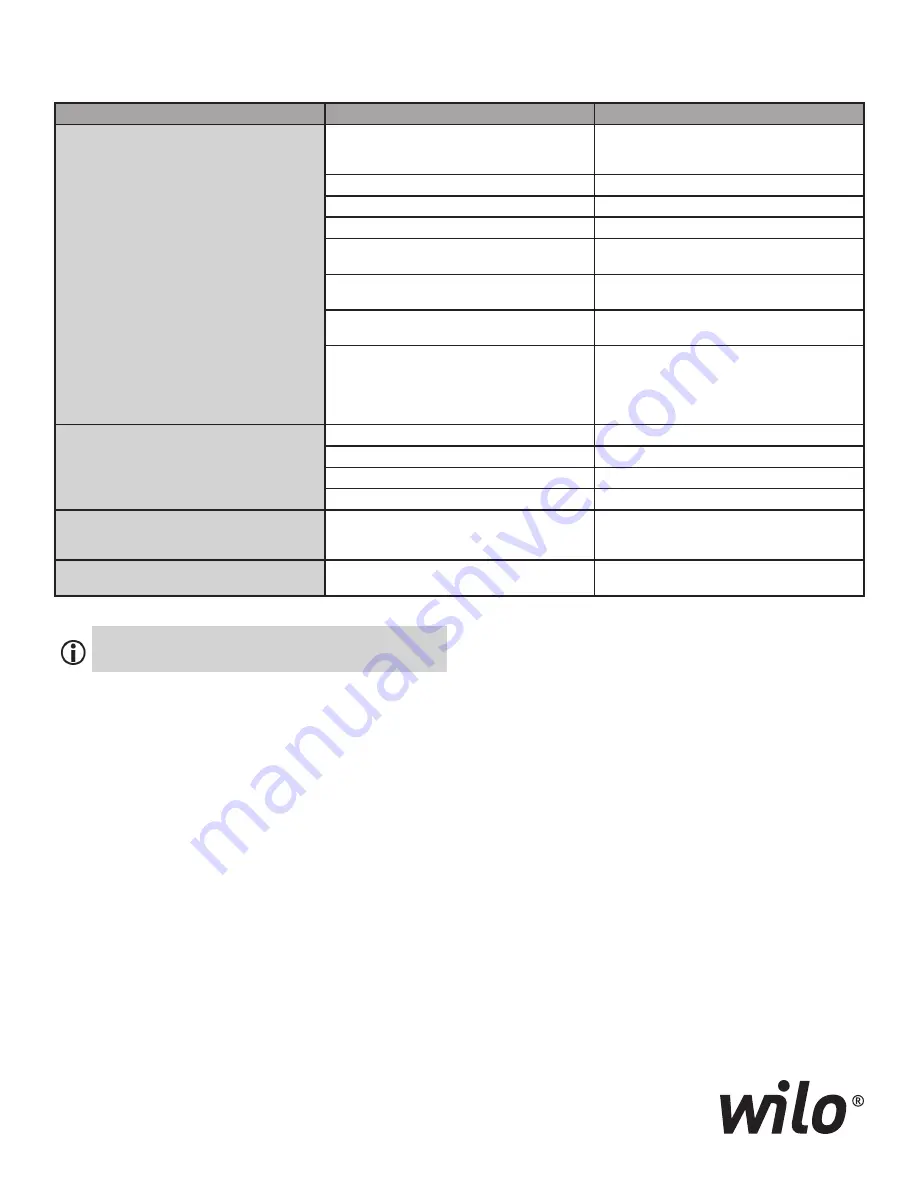
Faults

Possible Cause

Remedy

Pump does not start or fails to run

Pump Seized

Switch off power supply, take off pump head, 

remove obstruction; if motor blocked, overhaul/

exchange motor/ pump head

Loose Terminals

Tighten all terminals

Blown fuses/breakers

Check fuses, replace/reset as necessary

Faulty motor

Call service

Tripped overload relay (excessive amp draw)

Throttle hydraulic flow rate down to nominal on 

discharge side of pump

Incorrectly set trip relay (heaters)

Reset thermal overloads to full load current value 

specified on name plate

Thermal overload is influenced by excessive ambi

-

ent temperature

Prevent overloads caused by high ambient tem-

peratures

Tripped PTC relay

Check motor and fan cover for dirt/dust accu-

mulation and clean if necessary; Check ambient 

temperature and if necessary, ensure an ambient 

temperature

£ 105 °F [40 °C] by forced ventilation.

Pump runs at reduced capacity

Incorrect rotation

Check direction of rotation, reverse if necessary

Discharge valve throttled too far

Slowly open isolating valve

Speed too low

Adjust incorrect terminal bridging (Y in lieu D)

Air in suction pipe

Check and correct all possible suction leaks

Insufficient inlet pressure

Raise inlet pressure, ensure minimum required inlet 

pressure at suction port, check and if necessary 

clean suction-side isolating valve and strainer

Pump makes noise

Faulty motor bearings

Arrange for pump to be inspected and, if necessary, 

to be repaired by Wilo or other authorized service.

12. 

Troubleshooting Guide

Note: 

 If you cannot fix the problem, contact service 

engineer or a Wilo branch office.

Summary of Contents for Cronoline ICL

Page 1: ...Installation and operating instructions WILO_IOM_ICL_1219 Wilo Cronoline ICL Inline Close Coupled Pumps...

Page 2: ...Performance Regulation 6 Transport and Shipping 6 Mechanical Installation 7 Connect Condensate Drain 7 Electrical Connection 8 Fill and Ventilate 8 Check Direction of Rotation 9 Operation 9 Maintenanc...

Page 3: ...pping NPT 3 Air Vent 1 8 NPT 4 Lantern 5 Shaft 6 Motor 7 Cover plate Bolt 8 Condensate Drain Connection 9 Motor Frame Bolt 10 Lantern O ring 11 Mechanical Seal 12 Impeller 13 Impeller Belleville Washe...

Page 4: ...ent 1 8 NPT 5 Shaft 6 Motor 7 Cover plate Bolt 8 Condensate Drain Connection 9 Motor Frame Bolt 10 Lantern O ring 11 Mechanical Seal 12 Impeller 13 Impeller Keys 14 Fender Washer 15 Split Lock Washer...

Page 5: ...fications may be made to the pump Use only original spare parts Electrical Power Supply Working with electrical current could cause serious risk of bodily injury therefore 3 2 1 6 2 1 7 3 1 i ii iii i...

Page 6: ...eal to fail Note For additional data see type plate product information sheet or Wilo catalog Pump housing and lantern Cast Iron Class 30 ASTM A48 Ductile Iron ASTM A536 Impeller Bronze CC480K GS Pump...

Page 7: ...ue to high deadweight The pump itself and pump components may have a very high deadweight There is a risk of potentially fatal impact and crushing caused by falling parts Always use suitable lifting e...

Page 8: ...age Never operate the pump with incorrect voltage This could damage the motor 6 7 Connect grounding cable Install motor control cabling overload protection mains circuit breaker and accessories in acc...

Page 9: ...n by briefly turning it on The direction of rotation is correct if the fan or other visibly rotating parts of the pump are rotating in the direction of the arrow 2 On three phase only if the direction...

Page 10: ...screws on motor flange using torquewrench Torque L Page 11 Press new mechanical seal onto the shaft and into the lantern Use a small amount of approved polymer lubricant and press stationary section o...

Page 11: ...he pump Never operate a pump that is not correctly assembled This can damage the pump Torque 10 Location Material SAE Grade Diameter inches ft lb Nm Impeller Shaft Stainless steel 3 8 22 30 1 2 44 60...

Page 12: ...bi ent temperature Prevent overloads caused by high ambient tem peratures Tripped PTC relay Check motor and fan cover for dirt dust accu mulation and clean if necessary Check ambient temperature and i...

Reviews: