


8
WILO_IOM_ICL_1219
6.
7.
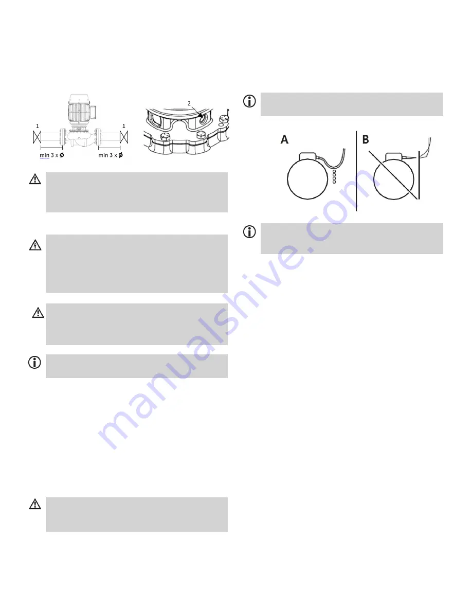
If desired, a condensate drain can be connected.
(2) Condensate drain for vertical installation
position of the motor
Seal up unused condensate drain.
7.
Electrical Connection
Caution: Damage due to overheating!
For insulated piping systems, only the pump volute
may be insulated, not the lantern and the motor. These
could be damaged by heat build-up.
Danger: Life threatening due to electrical shock!
Touching live parts can be fatal. Work on the electrical
connection may only be performed by a trained
electrician. Prior to connecting, ensure that the
connecting line is voltage-free.
7.1
Electrical Connection
1.
Connect the connecting cable with power
switched off and secure against reconnection.
2.
Lay the connecting cable such that it doesn’t
come into contact with the pump, the pump
housing, or the piping.
3.
Check whether the voltage and amperage in
the mains match the specifications on the type
plate of the pump.
Warning: Danger due to a damaged cable!
For pumps that pump hot liquids or that are used in
proximity to hot surfaces with temperatures above
194°F [90°C], a heat- resistant cable must be used.
Note:
For the correct cable size, refer to local wiring
restrictions.
Caution: Damage due to incorrect voltage!
Never operate the pump with incorrect voltage. This
could damage the motor.
6.
7.
Connect grounding cable.
Install motor control, cabling, overload
protection, mains circuit breaker and
accessories in accordance with the locally
applicable safety regulations.
4.
Open the terminal box.
5.
Lay the cable such that no condensation or
spray water can make contact with the cable
screws (Fig. A).
Note:
The connection diagram is located on an exterior
label or inside the terminal box.
Note:
Special motors can be supplied with a PTC
thermal sensor that must be connected to the PTC trip
relay.
8.
9.
10.
11.
7.1.1
To protect the motor, overheating protection
should also be installed.
Tighten cable screws
Close terminal box and ensure that no spraying
water can enter it.
Low temperature applications (below normal
temperature range) can be used with Glycol up
to a 50% concentration.
Caution when connecting to an automatic
pump control device
Comply with respective installation and
operating instruc- tions when wiring to
automatic pump control device (DDC or Building
Management Systems). Be sure the following
guidelines are met:
*AC power is within ±10% of rated voltage
with rated frequency (see motor name plate for
ratings)
or
*AC power is within ±5% of rated frequency
with rated voltage
or
*Combined variation in voltage and frequency
of ±10% (sum of absolute values) of rated
values, provided the frequency variation does
not exceed ±5% of rated frequency


