


DL107, DL207 and DL210 2.0 Digi-Loop™ DSP Induction Loop Amplifiers
28
All aspects of the loop amplifier can be configured from
the front panel GUI.
The on-board menus are navigated and adjusted using
a rotary encoder labeled “ADJUST” and by pushing the
knob in to “ENTER”.
There are a number of common operations:
To move to the next menu, turn the control clockwise.
It might be necessary to cycle through the on-screen
options until you get there. Clockwise moves forward;
counter-clockwise moves back.
Pressing the control knob in (“ENTER”) moves the
selection into that menu or option for further adjustment
or options.
To change values: ENTER - ADJUST - ENTER (no escape
or undo).
In order to exit a menu or option, select the “BACK”
command in the list.
The screen will return to the “Loop Status” menu after a
period of time.
Front Panel Controls
A572
Front LCD Menu (GUI) display
Headphone jack
USB
jack
Dante jack
(
“D”
models only)
Ethernet
jack
Mic/Line
level
inputs
Line
level
output
Spkr
level
input
Loop
output
Power
switch
Line cord
connection
Fuse
access
Loop fault
relay
Line
level
input
USB
jack
Dante jack
(
“D”
models only)
Ethernet
jack
Mic/Line
level
inputs
Line
level
output
Spkr
level
input
Loop
outputs
Power
switch
Line cord
connection
Fuse
access
Loop fault
relay
Line
level
input
Model &
Serial
numbers
Model &
Serial
numbers
Menu (GUI) display control knob
DL107/207
DL107
DL 207
Front Screen Menu Tree Detail
The entire on-screen menu is accessed by either rotating the control
knob to the left or right (to view), or pushing it in (to select).
See the Menu Tree (previous page) for an overview of the entire menu
structure.
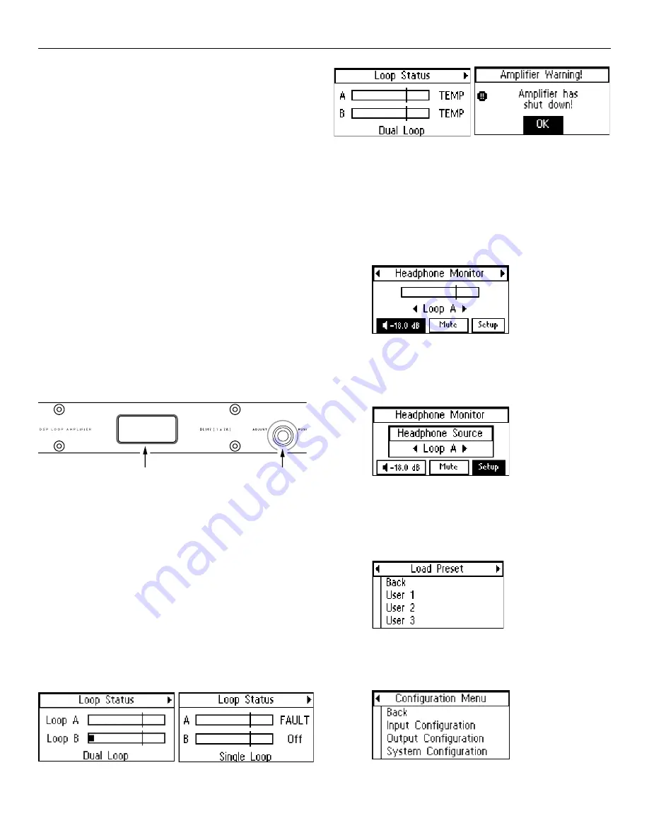
1. LOOP STATUS
The On-Screen Menu starts, and when it times-out, will return to
the “Loop Status” Screen (below). The bars represent the power
output of the loop(s), and will pulse with the audio program being
broadcasted on the loop (or speaker). The vertical lines going
through the bars represent the reference level of 0 dB.
Normal Condition:
Loop Fault (shorted or open):
Overtemp (loop impedance out of range):
2. HEADPHONE MONITOR
The Headphone monitor can be used to listen to any individual
source or output, or to listen to adjustments as they are made
in the menu. Rotate the knob once to the right to see the
Headphone Monitor screen. The vertical bar going through the
bar graph represents a reference level of 0 dB. You can change
the volume of the headphones or mute the audio from this
screen.
2a. Headphone Source
To change the headphone source, enter the Headphone Monitor
Setup. Rotate the knob to view the sources. Push the knob in to
select the source desired for the headphones.
3. LOAD PRESET
Presets provide the ability to save and recall custom configurations
(all amplifier settings). This is where a preset can be recalled, or
“
loaded”
. To
save
a Preset, see 7a2.
4. CONFIGURATION MENU
The configuration menu is where most of the amplifier settings and
fine-tuning is performed. This menu is where Inputs and Outputs are
configured and system parameters are set up, stored and recalled.
5. INPUT CONFIGURATION
The “Input Configuration” page allows the user to individually select


