Operating Instructions Temperature Indicating Controller CF1M
V1.
1
•
03/200
5
- 21 -
Heater burnout alarm [Option code: W1X]
Watches the heater current with CT (current transformer), and detects the burnout.
This option cannot be applied to the type current output.
When the option [SV2] or [CR5] is applied, the option [W1X] cannot be applied together.
Rating
: 5A [Option W10], 10A [Option W11],
20A [Option W12] or 50A [Option W15]
Setting range
: In the case of 5A, 0.0 to 5.0A
(off when set to 0.0)
In the case of 10A, 0.0 to 10.0A (off when set to 0.0)
In the case of 20A, 0.0 to 20.0A (off when set to 0.0)
In the case of 50A, 0.0 to 50.0A (off when set to 0.0)
Setting accuracy: ±5%
Input resolution : 1/200 of each rated value
Action
: ON/OFF action
Output
: Open collector
Control capacity, 24Vdc 0.1A (maximum)
Setting value memory (external selection) [Option code: SV2]
If this option is applied, the main setting value 1 or 2 can be changed by the external contact.
When the option [W1X] or [CR5] is applied, the option [SV2] cannot be added together.
When the contact open : Main setting 1
When the contact closed : Main setting 2
Terminal cover [Option code: KAB]
Electrical shock protecting terminal cover
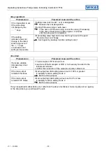
9. Troubleshooting
When troubled, refer to the following items after checking the power and the wiring.
<Indication>
Phenomenon
Presumed cause and the action
If PV/SV display is
indicating [
]
• Control output OFF function is working.
Press the
OUT
/
OFF
key for approx. 1s to release the function.
If [
] is blinking
on the PV/SV display
• Thermocouple or RTD is burnt out.
[In the case of Thermocouple]
If the input terminal of the instrument is connected,
and if nearby room temperature is indicated, the instrument
should be normal and sensor may be burnout.
[In the case of RTD]
If approx. 100
Ω
of resistance is connected to the input terminal
between A-B of the instrument and between B-B is connected,
and if nearby 0°C (32°F) is indicated, the instrument should
be normal and sensor may be burnout.
• Lead wire of thermocouple or RTD is not surely mounted to the
instrument terminal.
If [
] is blinking
on the PV/SV display
• Polarity of thermocouple or compensating lead wire is reverse.
• Codes (A, B, B) of RTD does not agree with the instrument terminal.
If indication of
PV/SV display is
abnormal or unstable.
• Designation of the Sensor input is improper.
• Temperature unit (°C or °F) is mistaken.
• Sensor correcting value is unsuitable.
Set the value suitably.
• Specification of the Thermocouple or RTD is improper.
• AC leaks into thermocouple or RTD circuit.
• There is a piece of equipment to send out inductive interference
or noise near the controller.


