23
3.
Faults and maintenance
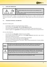
Make sure the box rotator is always in the lowest position during maintenance or repairs to the machine. Extra
measures can be taken, e.g. putting the locking pin behind the rotating cylinder and/or disconnecting the hydraulic
hoses
.
3.1
Preventive maintenance and lubrication
After the First 8 working hours:
-
Aansluitingen en wartels van de hydraulische slangen natrekken.
-
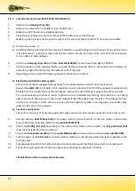
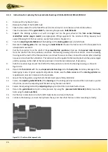
Check the bolts of the
locking plate
(100Nm)
and clamping strips
(140Nm).
-
Check the clamping bolts of the piston rod head of the rotating cylinder; these must be firmly secured.
-
Fasten the tap bolts on the
guide block
of the rotating cylinder tight (60 Nm), and secure using the lock nuts.
After every 40 working hours:
-
Check the bolts of the
locking plate
and tighten if necesarry (100Nm).
-
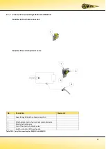
Clean and grease the gear Wheel and gear rack of the
rotating cylinder (2)
. Check both for wear and tear.
Replace after excessive wear and tear.
-
Check if there is any clearance between the cylinderhead and cylindertube.
-
Grease the rotating cylinder at the sliding strip of the
guide block
.
Check the tension of the guide block on the cylinder, readjust using the adjusting bolts, if necessary (60Nm),
and secure using the lock nuts.
Regularly check the hydraulic section for any leaks. Never try and search for leaks or stop a leak by hand.
Liquid under high pressure can easily penetrate skin and clothing, and may cause serious injuries. Replace
any damaged hydraulic hoses to prevent them from breaking and any accidents as a result.
Regularly check the oil level of the hydraulic system of your forklift truck / tractor.
NB:
Please read the instructions from the manual prior to any maintenance to the
machine!
Turn off the engine and remove the key from the ignition for the time maintenance
on the machine is carried out!
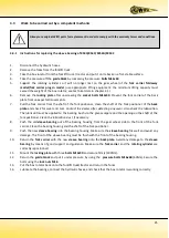
This sticker shows the position of a grease nipple on the machine. Lubricate the machine after every 10
working hours. Recommended lubricants include SAE 30 oil and Grade 2 grease based on lithium.
Summary of Contents for K54A-I
Page 2: ......
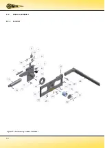
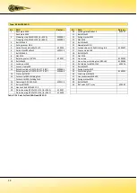
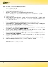
Page 12: ...10 2 2 K54A I and K54C I 2 2 1 Parts list Figure 2 2 1 Parts drawing for K54A I and K54C I...
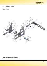
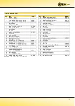
Page 15: ...13 2 3 K54A O and K54C O 2 3 1 Parts list Figure 2 3 1 Parts drawing for K54A O and K54C O...
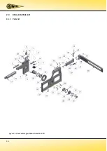
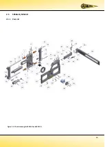
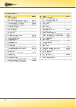
Page 18: ...16 2 4 K54A Z O K54C Z O 2 4 1 Parts list Figure 2 4 1 Parts drawing for K54A Z O and K54C Z O...
Page 21: ...19 2 5 SK54A O SK54C O 2 5 1 Parts list Figure 2 5 1 Parts drawing for SK54A O and SK54C O...
Page 29: ......
Page 30: ......
Page 31: ......

