22
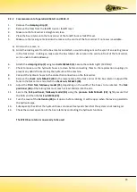
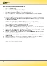
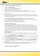
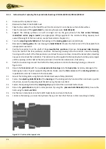
2.5.3 Commencement of operation SK54A-O and SK54C-O
1.
Remove the
clamping
strips
(18)
.
2.
Remove the forks from the forklift truck or forklift mast.
3.
Make sure the fork carrier is straight and clean.
4.
Place the box rotator onto the fork carrier of the forklift truck or forklift mast.
5.
Make sure the locking cam slots into the recess in the centre of the fork carrier. If no recess is available:
a)
Grind such a recess, or
b)
Grind the locking cam from the box rotator and attach a sound locking cam on the spot of an existing recess
in the fork carrier. In doing so, make sure the box rotator sits secure in the centre in front of the fork carrier,
so it is unable to slide sideways.
6.
Attach the
clamping strips (18)
with
four bolts M16x60 (20)
. Secure these bolts tight! (140 Nm)
7.
Check to make sure the hydraulic hoses are clean before connecting them to the rapid-action couplings, to
prevent any debris from entering the hydraulics of the machine.
8.
Depending on the model, the following hydraulic hoses are connected:
a)
Electrically controlled reversing valve:
Connect the hydraulic supply/discharge hoses to the dual-action connection on the fork carrier.
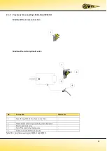
Mount the
switch (4)
, see chapter 2.5.2, supplied in such a location that the lifting equipment operator will
be able to turn it on and off from his control post, without the risk of mixing it up with any other controls.
For a safe working environment, avoid situations such as inadvertently starting the machine or not being
able to control it. Keep an eye on the correct voltage of the lifting device and the valve. The voltage is shown
on the coil. Connect a 2-core cable as per the electric diagram. Include a warning light, fuse and/or plug
socket in the circuit, if so required.
b)
Four-hose connection:
Connect the two pairs of hydraulic supply/discharge hoses to the dual-action connection on the fork carrier.
9.
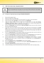
Remove the two
bolts M16x25 (29)
in the lower plate of the fork carrier of the box rotator. Suspend the
forks to the fork carrier and attach the two
bolts M16x25 (29).
10.
Adjust the
folding fork (49)
depending on the width of the boxes to be rotated. The
fork positioner (40)
must reach at least 150 mm into the slot.
11.
Secure the
fork positioner (40)
with two
bolts M16x45 (31)
and secure these with two
lock nuts M16 (30)
.
12.
Turn the lever of the
ball valve
so it opens, before rotating. It will be open when the lever is parallel to the
hydraulic pipe.
13.
Subsequently check that the hydraulic hoses can move freely and check that the system is not leaking oil.
14.
Check the correct operation of the box rotator by controlling the hydraulic functions.
The WIFO box rotator is now ready to be used.
Summary of Contents for K54A-I
Page 2: ......
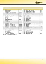
Page 12: ...10 2 2 K54A I and K54C I 2 2 1 Parts list Figure 2 2 1 Parts drawing for K54A I and K54C I...
Page 15: ...13 2 3 K54A O and K54C O 2 3 1 Parts list Figure 2 3 1 Parts drawing for K54A O and K54C O...
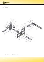
Page 18: ...16 2 4 K54A Z O K54C Z O 2 4 1 Parts list Figure 2 4 1 Parts drawing for K54A Z O and K54C Z O...
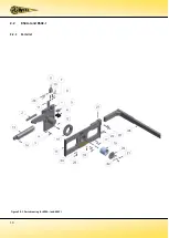
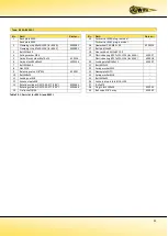
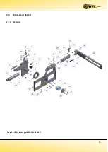
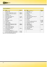
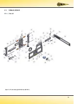
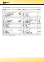
Page 21: ...19 2 5 SK54A O SK54C O 2 5 1 Parts list Figure 2 5 1 Parts drawing for SK54A O and SK54C O...
Page 29: ......
Page 30: ......
Page 31: ......


