Wiedenmann TERRA GROOM Translation Of Original Operating Instructions Download Page 42

All information, illustrations and specifications in these Operating Instructions are based on the latest information available at the time of 

publication. We reserve the right to make design changes at any time without prior notification


42

10.0. Technical Specifications 

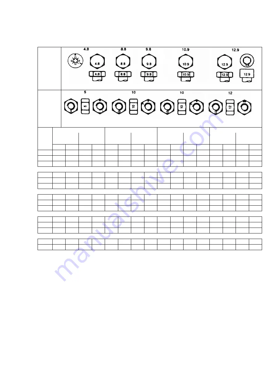
10.3. Metric bolt and cap screw torque values 


Property 
Class and 
Head 
Markings 


Property 
Class and 
Nut  
Markings 


class 4.8 

class 8.8 or 9.8 

class 10.9 

class 12.9 

Lubricated * 

Dry ** 

Lubricated * 

Dry ** 

Lubricated * 

Dry ** 

Lubricated * 

Dry ** 

 
Size 

N-m lb-ft N-m lb-ft N-m lb-ft N-m lb-ft N-m lb-ft N-m lb-ft N-m lb-ft N-m lb-ft 

M6  4,8 3,5 6  4,5 9  6,5 11  8,5 13  9,5 17  12  15  11,5 

19  14,5 

M8 12 8,5 15 11 22 16 28 20 32 24 40 30 37 28 47 35 
M10 

23 17 29 21 43 32 55 40 63 47 80 60 75 55 95 70 


M12 

40 29 50 37 75 55 95 70 110 

80 140 

105 

130 

95 165 

120 

M14 63  47  80  60  120 88  150 110 175 130 225 165 205 150 260 190 
M16 100 73  125 92  190 140 240 175 275 200 350 255 320 240 400 300 


M18 135 100 175 125 260 195 330 250 375 275 475 350 440 325 560 410 
M20 190 140 240 180 375 275 475 350 530 400 675 500 625 460 800 580 
M22 260 190 330 250 510 375 650 475 725 540 925 675 850 625 1075 800 


M24 330 250 425 310 650 475 825 600 925 675 1150 

850 1075 

800 1350 1000

M27 490 360 625 450 950 700 1200 875 1350 1000 1700 

1250 

1600 

1150 2000 1500

M30 675 490 850 625 1300 950 1650 1200 1850 1350 2300 

1700 

2150 

1600 2700 2000


M33  900  675  1150 850  1750 1300 2200 1650 2500 1850 3150 2350 2900 2150 3700 2750
M36  1150 850  1450 1075 2250 1650 2850 2100 3200 2350 4050 3000 3750 2750 4750 3500


DO NOT use these values if a 
different torque value or tightening 
procedure is given for a specific 
application. Torque values listed are 
for general use only. Check tightness 
of fasteners periodically. 

Shear bolts are designet to fail 
under predetermined loads. Always 
replace shear bolt with identical 
property class 

Fasteners should be replaced with the 
same or higher property class. If 
higher property class fasteners used, 
these should only be tightened to the 
strength of the original. 


Make sure fasteners threads are 
clean and that you properly start 
thread engagement. This will 
prevent therm from failing when 
tightening. 

Tighten plastic insert or crimped 
steel-type lock nuts to 
approximately 50 percent of the dry 
torque shown in the chart, applied 
to the nut, not to the bolt head. 
Tighten toothed or serrated-type 
lock nuts to the full torque value. 

**    “Lubricated“ means coated with a lubricant such as engine 

oil, or fasteners with phossphate and oil coatings. 

**    “Dry“ means plain or zinc platend without any 

lubrication. 


Summary of Contents for TERRA GROOM

Page 1: ...Translation of original Operating Instructions Sand brush TERRA GROOM 515 002 From equipment I D No 515 AA 1001 Status January 2012 515 99 01...

Page 2: ...ustrations and specifications in these Operating Instructions are based on the latest information available at the time of publication We reserve the right to make design changes at any time without p...

Page 3: ...ustrations and specifications in these Operating Instructions are based on the latest information available at the time of publication We reserve the right to make design changes at any time without p...

Page 4: ...depending on the layout and the used synthetic turf We recommend that you consult with your groundsman or synthetic turf manufacturer to clarify the suitability of maintenance machines before usage T...

Page 5: ...port of the TERRA GROOM 22 4 0 Connecting to the tractor 23 25 4 1 General information 23 4 2 Mounting with three point hitch 23 4 3 Mounting with drawgear 24 4 4 Support for drawbar 24 4 5 Ballast 25...

Page 6: ...y instructions contained in these operating instructions as well as all those attached to the machine The warning signs must be kept in good condition i e readable Replace missing or damaged warning s...

Page 7: ...te safety equipment for the work at hand Prolonged exposure to loud noise can result in impairment or loss of hearing Wear a suitable hearing protective device such as earmuffs or earplugs A safe oper...

Page 8: ...adjusting or cleaning as well as connecting or disconnecting the PTO driven machines EXERCISE CAUTION IN THE CASE OF LINE LEAKAGE Leaking high pressure fluids can penetrate the skin and cause serious...

Page 9: ...g turns Ensure safe traffic conditions by using hand signals or indicators Use headlights hazard warning lights indicators and other safety equipment i a w the respective legal provisions Keep safety...

Page 10: ...fumes and dust Hazardous fumes can be generated when paint is heated due to welding soldering or using a welding torch All work is to be performed outdoors or in a well ventilated area Dispose of pai...

Page 11: ...ing symbols indicating danger are attached at some important areas on the machine The hazard is identified via a warning triangle A second symbol informs you how the injury can be prevented by acting...

Page 12: ...It is too late to do this when you have started work In the working area the user is responsible for the safety of other persons During operation on public highways the relevant traffic regulations mu...

Page 13: ...The machine must only be attached when the engine is shut off and the PTO shaft drive is switched off The warning and information signs on the machine contain important information to ensure safe oper...

Page 14: ...the supports 2 3 1 Three point hitch version Both parking supports A are to be secured to the square pipes of the basic unit so that no bristles are touching the ground when the machine is in the park...

Page 15: ...it using locking bolt B To secure screw in screw C Secure turnbuckle D on basic unit using screw E 2 6 Mounting electric lifting equipment for chassis Secure electro spindle A on chassis C using screw...

Page 16: ...Hold the strip brushes from underneath in the guide Manually screw in long hexagon head screws A with washers at the straight guides Manually screw in short hexagon head screws B with washers at the...

Page 17: ...at the time of publication We reserve the right to make design changes at any time without prior notification 17 2 0 Assembly 2 8 Mounting the spherical coupling Release fixing screws A and remove wi...

Page 18: ...llator may no longer function under certain circumstances Please maintain sufficient distance to the magnets if you have a pacemaker defibrillator Please warn all persons who have these devices agains...

Page 19: ...led version The magnetic bar is attached to the front lugs of the basic unit Slide the brackets of the magnetic bar onto lugs E and securely screw on Remove set screw F for swivelling the magnetic bar...

Page 20: ...2 0 Assembly 2 10 Mounting the decompaction brush set Remove the brush strips in the front support A washer and snap ring are required for the new installation Place plate A on brush strip B and alig...

Page 21: ...cranes or hoisting gear with sufficient lifting capacity Never stand under lifted loads There is an imminent danger to life if the load falls Improper transport and mounting of the TERRA GROOM can res...

Page 22: ...ansport 3 2 Transport of the TERRA GROOM 3 2 1 Transport Using a Forklift If the TERRA GROOM is still secured on the transport frame Insert the forks under the transport frame pay attention to the dir...

Page 23: ...t rolling away The following is required for attaching the machine Tractors with at least 9 kW 12 hp Hydraulic three point hoist cat 1 or connection point for drawbar 4 2 Installation with three point...

Page 24: ...ting to the Tractor 4 3 Mounting with drawbar Insert drawbar on tractor and secure For a description of the setting please see Chapter 6 2 If your tractor is not equipped with such a socket please con...

Page 25: ...the front axle load ensure that the permissible axle load weight as well as the permissible overall weight including the mounted equipment is not exceeded 4 6 Electric connection to battery Only appr...

Page 26: ...erforming any work The ignition key must be removed Secure the tractor against rolling away Always park on a paved and even surface when detaching the machine 5 2 Removal with three point hitch Before...

Page 27: ...e at the time of publication We reserve the right to make design changes at any time without prior notification 27 5 0 Disconnecting from the Tractor 5 3 Removal with trailer version Lower support at...

Page 28: ...to the information provided in these Operating Instructions please also observe generally applicable safety and accident prevention standards CAUTION The equipment version with a drawbar is NOT approv...

Page 29: ...h a three point frame the rear hydraulic system of the tractor must always be in the floating position during operation The ground must be dry for the use of the Terra Groom Use of the Terra Brush req...

Page 30: ...ve faulty Replace Due to regular work in the same direction Turn strip brushes at certain intervals see Chapters 7 4 and 8 5 Strip brushes deformed Temperature influence during work Gap between strip...

Page 31: ...ailable at the time of publication We reserve the right to make design changes at any time without prior notification 31 7 0 Operation 7 4 Deformed strip brushes We recommend that your turn all strip...

Page 32: ...disassembly tasks Switch off the engine before performing any work The ignition key must be removed Apply the parking brakes to ensure the tractor does not roll away 8 2 Lubrication Switch off the ma...

Page 33: ...im parts Always ensure the tyre pressure is correct and do not exceed the maximum pressure stated Check the wheels and tyres daily for underpressure incisions protrusions and swellings or damaged rims...

Page 34: ...8 0 Maintenance 8 5 Replacing strip brushes The strip brushes must always be replaced in sets Release hexagon screws A Replace strip brush Screw hexagon screws A in manually Align strip brushes Firml...

Page 35: ...s the machine might tilt and crush someone Disassembly for disposal 1 Place the equipment on firm ground 2 Disassemble the machine working from top to bottom NOTE Strictly observe the regulations and...

Page 36: ...9 1 Scope of Delivery Basis unit Chassis with drawbar and electric hoist or three point linkage Brush set selective Operating instructions transfer declaration with guarantee card 9 2 Machine designs...

Page 37: ...tion We reserve the right to make design changes at any time without prior notification 37 9 0 Equipment 9 3 Special equipment Spherical coupling Only for trailed version Decompaction brush set Only s...

Page 38: ...ion A Working width 1880 mm B Machine width 1880 mm C Height of device in parked position 600 mm D Device length from lower guide bar connection 975 mm E Device length with magnetic bar 1355 mm F Heig...

Page 39: ...nstructions are based on the latest information available at the time of publication We reserve the right to make design changes at any time without prior notification 39 10 0 Technical Specifications...

Page 40: ...ine width 1880 mm C Machine height in working position 560 mm D Height of device in parked position 600 mm E Machine length with chassis and drawbar 2050 mm F Device length with chassis and spherical...

Page 41: ...ating Instructions are based on the latest information available at the time of publication We reserve the right to make design changes at any time without prior notification 41 10 0 Technical Specifi...

Page 42: ...5 675 1150 850 1075 800 1350 1000 M27 490 360 625 450 950 700 1200 875 1350 1000 1700 1250 1600 1150 2000 1500 M30 675 490 850 625 1300 950 1650 1200 1850 1350 2300 1700 2150 1600 2700 2000 M33 900 67...

Page 43: ...We reserve the right to make design changes at any time without prior notification 43 10 0 Technical Specifications 10 4 Chassis Number Enter the respective product identification no in the space pro...

Reviews: