background image

Terra Clean 100 

4   Machine description 


10 | 2020 

239 99 01 

 003 

27 


4.3.1.


Torques for metric screws 


Class and 
markings of the 
screw heads 


Class and 
markings of the 
nuts 


Size 

Class 4.8 

Class 8.8 oder 9.8 

Class 10.9 

Class 12.9 

Lubricated * 

Dry ** 

Lubricated * 

Dry ** 

Lubricated * 

Dry ** 

Lubricated * 

Dry ** 

Nm 

lb-ft 

Nm 

lb-ft 

Nm 

lb-ft 

Nm 

lb-ft 

Nm 

lb-ft 

Nm 

lb-ft 

Nm 

lb-ft 

Nm 

lb-ft 

M6 

4,8 

3,5 

4,5 

6,5 

11 

8,5 

13 

9,5 

17 

12 

15 

11,5 

19 

14,5 

M8 

12 

8,5 

15 

11 

22 

16 

28 

20 

32 

24 

40 

30 

37 

28 

47 

35 

M10 

23 

17 

29 

21 

43 

32 

55 

40 

63 

47 

80 

60 

75 

55 

95 

70 


M12 

40 

29 

50 

37 

75 

55 

95 

70 

110 

80 

140 

105 

130 

95 

165 

120 

M14 

63 

47 

80 

60 

120 

88 

150 

110 

175 

130 

225 

165 

205 

150 

260 

190 

M16 

100 

73 

125 

92 

190 

140 

240 

175 

275 

200 

350 

255 

320 

240 

400 

300 


M18 

135 

100 

175 

125 

260 

195 

330 

250 

375 

275 

475 

350 

440 

325 

560 

410 

M20 

190 

140 

240 

180 

375 

275 

475 

350 

530 

400 

675 

500 

625 

460 

800 

580 

M22 

260 

190 

330 

250 

510 

375 

650 

475 

725 

540 

925 

675 

850 

625 

1075 

800 


M24 

330 

250 

425 

310 

650 

475 

825 

600 

925 

675 

1150 

850 

1075 

800 

1350  1000 

M27 

490 

360 

625 

450 

950 

700 

1200 

875 

1350 

1000 

1700 

1250 

1600 

1150 

2000  1500 

M30 

675 

490 

850 

625 

1300 

950 

1650 

1200 

1850 

1350 

2300 

1700 

2150 

1600 

2700  2000 


M33 

900 

675 

1150 

850 

1750 

1300 

2200 

1650 

2500 

1850 

3150 

2350 

2900 

2150 

3700  2750 

M36 

1150 

850 

1450 

1075 

2250 

1650 

2850 

2100 

3200 

2350 

4050 

3000 

3750 

2750 

4750  3500 


The torques in this table are guidelines and do NOT apply where a 
different torque for certain screws or nuts is given in this 
instruction manual. Check tightness of fasteners periodically. 
Shear bolts are designed to fail under predetermined loads. 
Always replace shear bolt with identical property class. 
Fasteners should be replaced with the same or higher property 
class. If higher property class fasteners are used, these should 
only be tightened to the strength of the original. 


Make sure fasteners threads are clean and that you 
properly start thread engagement. This will prevent them 
from failing when tightening. 
Tighten plastic insert or crimped steel-type lock nuts to 
approximately 50 % of the dry torque shown in the chart, 
applied to the nut, not to the bolt head. Tighten toothed 
or serrated-type lock nuts to the full torque value. 
 

*   "Lubricated" means coated with a lubricant such as engine oil, 
or fasteners with phosphate and oil coatings. 


**  "Dry" means plain or zinc plated without any lubri-
cation. 


Summary of Contents for Terra Clean 100

Page 1: ...Translation of original operating instructions EN Synthetic Turf Maintenance Machine Terra Clean 100 Document number 239 99 01 003 From equipment I D No Status 10 2020...

Page 2: ...d observe the safety information Keep these operating instructions in a safe place 1 Manufacturer Wiedenmann GmbH Tel 49 7345 953 0 Am Bahnhof Fax 49 7345 953 233 89192 Rammingen info wiedenmann de DE...

Page 3: ...of this machine your dealer performed a pre delivery inspection to ensure optimal performance In the interest of further developing the machine we reserve the right to make those changes to individual...

Page 4: ...3 1 Obligation of the operator 10 3 2 Obligation of the operator 10 3 3 Intended use 10 3 4 Foreseeable incorect use 10 3 5 Service life of the machine 11 3 6 General safety instructions 11 3 6 1 Per...

Page 5: ...ar left view 23 4 1 3 Agitator unit internal view 24 4 2 Nameplate 24 4 2 1 Chassis number 24 4 3 Technical specifications 25 4 3 1 Technical data sheet 26 4 3 1 Torques for metric screws 27 4 4 Opera...

Page 6: ...on and off 38 9 3 1 Switching on the drive 38 9 3 2 Switching off the drive 38 9 4 Emptying the Dirt Container 38 10 Detaching from the tractor 39 10 1 Safety instructions for dismantling the tractor...

Page 7: ...sable you can use the document number on the cover sheet to request a replacement The document can also be downloaded via the Wiedenmann homepage www wiedenmann com 2 3 Applicable documents Alongside...

Page 8: ...ure This arrow represents an action step Multiple arrows in succession represent a sequence of actions that is to be performed one step at a time This symbol represents a prerequisite that must be met...

Page 9: ...rous situation that could lead to serious injuries or even death if the warning message is not observed CAUTION The signal word CAUTION warns of a dangerous situation that could lead to minor or moder...

Page 10: ...operator determines that a safety device is not in perfect working order this defect must be rectified immediately or the issue reported to the superior operator 3 3 Intended use This machine is desi...

Page 11: ...responsible for the safety of other persons Before moving off ensure that the immediate area of the machine is clear e g no children nearby Ensure that your visibility is not impaired Keep all person...

Page 12: ...cidents all persons performing work in line with these instructions must meet the following minimum requirements They must be a qualified specialist with corresponding training They must be capable of...

Page 13: ...hine can hit and potentially injure any persons riding along on the machine Never allow anyone to ride along on the machine 3 6 8 Operational reliability perfect technical condition Operation only aft...

Page 14: ...op Technical limits The machine can be damaged if its technical limits are not observed This can then lead to a risk of serious or even fatal injuries Observing the following limits is particularly im...

Page 15: ...s covering machine parts that were removed and then move them into their guard position If you are in any doubt as to whether all guards have been fitted properly and are working as they should commis...

Page 16: ...off valves of the machine s hydraulic system between the tractor and machine Prior to any road travel move the tractor s control units to their neutral position and lock them in place 3 6 12 Risk of...

Page 17: ...n can lead to health conditions such as hearing impairment deafness or tinnitus When using the machine at high speed the noise level is also increased Before commissioning the machine first assess the...

Page 18: ...jeopardises the operational reliability of the machine This can then lead to a risk of serious or even fatal injuries Never weld any of the following parts Gearboxes Components of the hydraulic system...

Page 19: ...chine parts secure the respective machine or machine parts and prevent them from descending using a rigid safety prop or hydraulic locking device e g stop valve and suitable supports To securely suppo...

Page 20: ...ickers Operating Instructions These operating instructions contain all important information necessary for safe machine operation Carefully observe all safety instructions to avoid accidents Read oper...

Page 21: ...21 3 8 2 Safety devices DANGER Risk of injury due to missing safety devices Never operate the machine without safety devices 3 8 3 Position of safety devices 1 Guard plates over the drive mechanism o...

Page 22: ...99 01 003 10 2020 4 Machine description 4 1 Machine overview 4 1 1 Front right view 1 Covering hood 6 Drawbar 2 Transport Using Crane 7 Fishplate 3 Securing points for transport on a trailer 8 Vehicl...

Page 23: ...4 1 2 Rear left view 1 Fishplate 8 Adjustable central working height 2 Support 9 Vehicle chassis 3 Transport Using Crane 10 Securing points for transport on a trailer 4 Tension jack 11 Drawbar 5 Cover...

Page 24: ...ts documented values and must not be changed damaged or otherwise concealed The machine data is printed on the nameplate 1 The nameplate is fitted on the right hand side of the machine chassis 4 2 1 C...

Page 25: ...rking width 1200 mm F Track width 1555 mm Drive speed at 8 km h Cylinder broom working speed ca 680 min 1 Eccentric shaft working speed ca 680 min 1 Min power required for tractor 12 KW 16 PS Operatin...

Page 26: ...Terra Clean 100 4 Machine description 26 239 99 01 003 10 2020 4 3 1 Technical data sheet B E 239 32 F A D C...

Page 27: ...000 1500 M30 675 490 850 625 1300 950 1650 1200 1850 1350 2300 1700 2150 1600 2700 2000 M33 900 675 1150 850 1750 1300 2200 1650 2500 1850 3150 2350 2900 2150 3700 2750 M36 1150 850 1450 1075 2250 165...

Page 28: ...to wear personal protective equipment poses a risk of injury Wear personal protective equipment See Section 3 6 10 Personal protective equipment 5 2 Unpacking the machine The transport frame is made...

Page 29: ...ort frame DANGER Danger to life due to falling load Only use a forklift truck with sufficient load capacity to raise the machine Never stand under lifted loads Improper transportation and attachment o...

Page 30: ...drawbar See chapter 5 3 Installing the drawbar Couple the tractor Roll the machine off the shipping frame 6 2 2 Transport Using a Crane The following 3 points on the attachment device enable it to be...

Page 31: ...Always adapt your driving style to match the terrain and ground conditions Special care should be taken when working and turning on a slope Take into account unevennesses of the ground bumps The foll...

Page 32: ...hine to adjustable drawbar and secure Set tension jack 1 to the appropriate function See chapter 8 2 3 Setting the agitator unit tilt angle For transporting the machine to or from a place of use set t...

Page 33: ...the drive on and off Secure covering hood 1 with tensioning belt lock 2 Set the central working height 1 to the T position transport position 2 8 Before initial operation 8 1 General information befo...

Page 34: ...condition of the ground or the compression of the granulate you may need to set the correct working position tooth by tooth INFO Check the setting after a few metres Adjusting by one tooth results in...

Page 35: ...ent plate setting for dry conditions new or highly filled grounds with low dirt proportion on regularly maintained grounds with low proportion of coarse dirt for deep surface cleaning Position in the...

Page 36: ...urface cleaning Position nach hinten abfallend grounds which are not regularly maintained with broken fibre content for dry conditions and flat surface cleaning for flat processing with leaf coverage...

Page 37: ...al information on operation ATTENTION Material damage due to incorrect treatment of the lawn Obtain approval for treatment from groundsman or synthetic grass manufacturer If the work setting is too lo...

Page 38: ...he lever 1 to pull the carrier shaft 2 outwards slightly Turn the lever 1 in the direction of the deep groove and lock in place 3 Slow movement causes the carrier shaft 2 to lock in the final position...

Page 39: ...mantling the tractor DANGER Risk of injury due to the machine rolling away Before disconnecting the machine from the tractor secure it with chocks to prevent it from rolling away See Section 3 7 1 Shu...

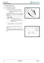
Page 40: ...ed Prior to performing any servicing maintenance or cleaning work shut down the engine and remove the ignition key Secure the tractor to prevent it from rolling away parking brake DANGER Risk of injur...

Page 41: ...excluded from the manufacturer s liability 11 2 Maintenance tables 11 2 1 Maintenance table staggered in time Maintenance interval Maintenance measure Area First use after 5 hours Check all moving par...

Page 42: ...orated mesh in collecting tray 11 4 Cylinder broom 11 4 1 Cleaning the cylinder broom CAUTION Risk of injury during maintenance Cleaning must only be carried out using hand brushes or water never with...

Page 43: ...th the plates 2 Remove and check the strip brush 3 In the case of slightly deformed brush rails these can be reinstalled turned through 180 In the case of severely deformed brush rails all brush rails...

Page 44: ...servicing maintenance or cleaning work shut down the engine and remove the ignition key To retension the chain proceed as follows Park the tractor and remove the ignition key Remove the cover 1 from t...

Page 45: ...you can stand to one side when inflating the tyres CAUTION Risk of accident during tyre fitting Only carry out tyre installation if you have appropriate experience and equipment Regularly check the t...

Page 46: ...5 km h Gap is too wide between baffle plate and brushes Check brushes if necessary replace strip brushes see section 11 4 2 Cylinder broom set too high Set the adjustment one tooth deeper or where app...

Page 47: ...ds reduce speed to below 5 km h Absorption brush is set too deep When adjusting to one tooth deeper if necessary only carry out fine adjustment on the tension jack Take account of the maximum working...

Page 48: ...edges crushing if machine topples Place the machine on firm ground Disassemble the machine from top to bottom ATTENTION Incorrect disposal of environmentally hazardous substances Regulations and laws...

Page 49: ...Terra Clean 100 14 Equipment 10 2020 239 99 01 003 49 14 2 Additional equipment 14 2 1 Riddle screens Riddle screen with 5 mm holes Riddle screen with 8 mm holes 14 2 2 Harrow 14 2 3 Rear brush...

Page 50: ...relevant basic safety and health requirements of the machinery directive 2006 42 EC Rammingen the 27 09 2013 Horst Wiedenmann Place and date of issue Managing Partner Name function and signature of au...

Page 51: ...nthetic Turf Maintenance Machine Terra Clean 100 referred to by this declaration complies with the requirements of Machinery Directive 2006 42 EC Rammingen den 05 10 2020 Oliver Matthes Place and date...

Reviews: