


BlueGate 2100
Installation
July 26, 2001
WIDCOMM, Inc, Proprietary and Confidential
3
3 Installation
Before installing BlueGate 2100, you should be familiar with basic local area network
(LAN) and Bluetooth concepts.
For a non-technical overview of key Bluetooth concepts refer to
3.1 P
OWER
C
ORD AND
E
THERNET
C
ABLE
I
NSTALLATION
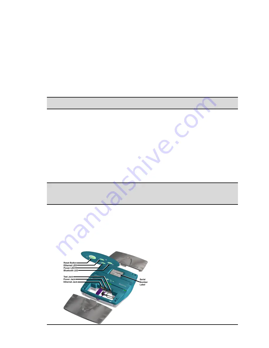
1. Mount BlueGate 2100 on the wall or ceiling or place it on a flat surface away
from heat, moisture, open flames, microwave devices, and 2.4 GHz
telecommunication devices (for example, 802.11b LAN adapters). See also the
RF Exposure Statement on page i.
NOTE: See Section 3.2 for additional information on mounting BlueGate 2100 on the wall
or ceiling.
2. Use the Ethernet cable provided in the kit to connect BlueGate 2100 to the local
area network. See Figure 1 for the location of BlueGate 2100’s Ethernet jack.
The Ethernet cable can be plugged into a network switch or network hub, or into
a hardwired wall jack that connects to the network. Consult your network
administrator if you are unsure of where or how to establish a physical
connection to the network.
Place the other end of the Ethernet cable securely into the Ethernet jack (RJ-45
connector) on BlueGate 2100. The Ethernet LED blinks off and on depending on
Ethernet activity.
Route the network cable away from other cables that may cause electrical
interference. Avoid routing the cable through areas where it will be stepped on,
tripped over, or damaged in any way.
NOTE: Telephone cables often use the same type of connector as network cables; some
wall plates, especially in office environments, have both telephone and network
jacks in the same wall plate. When connecting through a wall plate of this type
verify the physical connection between the jack and the network.
3. Insert the small circular power plug into the power jack on the back of
BlueGate 2100 and then plug the power supply into a wall outlet (120-220VAC,
60-50 Hz). When power is applied the bottom light emitting diode (LED) will
blink for 6 seconds and then stay on continuously.
If the LAN is 10Base-T or 100Base-T and a Dynamic Host Configuration Protocol
(DHCP) server is available, BlueGate 2100 is ready to use.
Figure 1: BlueGate 2100 connector and LED locations.