background image

15

13.

Lock push-fit collars using the
push-fit release/lock tool
using the single end to lift the
grey locking collars.

14.

Insert 2 Blanking Plugs into
unused inlets by pushing in
firmly and lock using tool.

15.

Before making any electrical
connection turn on water
supplies and check supply
connections for leaks.

16.

Feed mains cable through
cable clamp and connect
electrical supply to marked
terminals in the following
manner:

L - Live terminal block
N - Neutral terminal block
E - Earth stud screw

17.

Ensure that all terminal
connections are tight and that
no insulation is pinched.

18.

Secure the cable clamp to
prevent strain on the terminal
block.

Warning!

 Do not switch on the

electrical supply until the

COMMISSIONING

 has been

completed and the cover securely
fitted.

Summary of Contents for THERMOSTATIC POWER SHOWER

Page 1: ...1 PRODUCT MANUAL INSTALLER Please leave this manual with the user for future reference to unit operation and maintenance THERMOSTATIC POWER SHOWER 1 2 3 4 5 Power Mixer 6 7 AQUATRONIC back...

Page 2: ...justable spray handset with three settings flexible hose adjustable slider soap dish sliding rail and bracket WARNING This appliance must be earthed The shower unit must not be connected to a Mains Co...

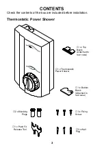
Page 3: ...allation Thermostatic Power Shower 2 x Blanking Plugs 1 x Thermostatic Power Shower 3 x Fixing Screw 1 x Bottom Blank Attached to rear case 1 x Top Blank Attached to rear case 3 x Wall Plug 1 x Push F...

Page 4: ...the device will cut the power to the motor but will self reset once temperatures have normalised Noise Level The acoustic noise from the pump motor has been reduced with integral foam rubber mounting...

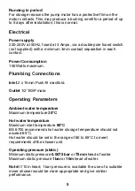
Page 5: ...nlet 2 x 15mm Push fit manifold Outlet 1 2 BSP male Operating Parameters Ambient water temperature Maximum temperature 30 C Hot water temperature Maximum inlet temperature 80 C BS 6700 recommends hot...

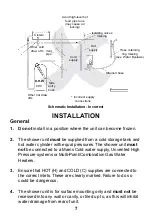
Page 6: ...ards This Thermostatic Power Shower complies with all relevant directives for CE marking Schematic Installation Correct 25mm minimum Warning pipe Cistern Minimum 1 0m head Minimum 22mm Isolating valve...

Page 7: ...rozen 2 The shower unit must be supplied from a cold storage tank and hot water cylinder with equal pressures The shower unit must not be connected to a Mains Cold water supply Unvented High Pressure...

Page 8: ...e live and neutral conductors as this will prevent them from entering the terminal block 5 Make sure that any pipework that could become frozen is properly insulated The shower unit must not be fitted...

Page 9: ...fore making any electrical connections 14 Ensure all electrical connections are tight to prevent overheating Caution 1 Read all of these instructions and retain this guide for later use 2 Pass on this...

Page 10: ...tions Bylaws Scotland Building Regulations or any particular regulations and practices specified by the local water company or water undertakers The installation should be carried out by a plumber or...

Page 11: ...age the Push fit seals 9 If plated tubing is used for inlet pipework remove 25mm of plating to ensure good seal Stainless steel piping MUST not be used 10 15mm polythene plastic pipe suitable for hot...

Page 12: ...to reveal cover securing screw 2 Unscrew cover securing screw and lift cover from bottom to remove 3 Hot and cold inlet supply connections as marked are Hot Left Cold Right Note Reversed supply connec...

Page 13: ...he end of the pipe to assist insertion into the fitting and prevent tearing the O seal 5 Locate base unit onto inlet supplies against the wall in the chosen position Ensure that minimum head pressure...

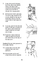
Page 14: ...ing fixed to Ensure correct type of wall plugs are used 9 Cut away and trim the thinned section at the top or bottom of the case to allow electrical supply cables to run down rear of case 10 Route the...

Page 15: ...k supply connections for leaks 16 Feed mains cable through cable clamp and connect electrical supply to marked terminals in the following manner L Live terminal block N Neutral terminal block E Earth...

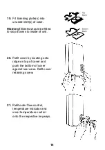
Page 16: ...e fitted to stop access to inside of unit 20 Refit cover by locating onto ridge on top of cover and push the bottom of cover against rear case Refit cover retaining screw 21 Refit outer flow control t...

Page 17: ...trical supply 1 Connect the flexible hose only to the shower outlet of the unit Caution Do not over tighten 2 Turn on the water supplies Do not turn on electrical supplies 3 Turn the outer flow contro...

Page 18: ...ow should be followed 1 Turn outer flow control anticlockwise to full on 2 Turn the inner temperature control lever anticlockwise until maximum rotation has been achieved 3 Check temperature 4 If temp...

Page 19: ...site conditions and user s comfort 1 Turn the outer flow control knob until the desired flow of water is obtained The flow of water will increase the further the control is turned 2 Turn the inner tem...

Page 20: ...function Maximum shower temperature too hot Shower temperature too cold Blend temperature unstable Low or no water flow Shower runs cool after a short time 1 2 minutes then flow splutters Cause Incorr...

Page 21: ...tres Insufficient storage of hot water in cylinder Insufficiently sized pipework for both systems to be used together Electrical supply failure Micro switch failure Pcb failure Motor overheated therma...

Page 22: ...ning Inlet filters Warning Isolate the electrical and water supplies before proceeding 1 Remove unit controls and front cover see INSTALLATION 2 Remove retaining screw and filter cap 3 Remove filters...

Page 23: ...419 50 209 72 A 419 49 A A A A A A A A A B B 209 72 Filter Pack 209 73 Screw Pack components identified A 209 75 Seal Kit components identified B 211 38 Thermostatic Valve Assy 209 79 Manifold Assy 41...

Page 24: ...ordance with this manual If the fault can not be resolved please contact the Customer Service Department who will try to assist or will arrange a local Service Engineer or Agent to call and arrange a...

Reviews: