


700 SERIES LAWN TRACTORS
2
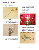
2.
DECK REMOVAL
2.1.
The engine should be turned off long enough for
the exhaust system to cool before starting work.
2.2.
The controls should be in the following positions:
PTO lever: OFF Deck height: lowest position
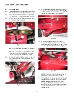
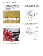
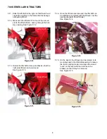
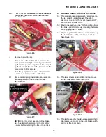
2.3.
Remove the crankshaft pulley belt keeper using
a 1/2” wrench. See Figure 2.3.
NOTE:
The belt keeper doubles as the deck up-
stop.
NOTE:
The correct place for the pin-end of the
belt keeper is the small hole in the right frame
channel, roughly in-line with the crankshaft.
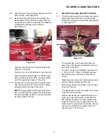
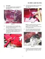
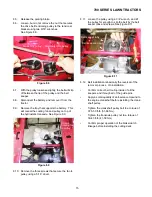
2.4.
Remove the hairpin clips that secure the deck lift
rods to the cutting deck and the deck lift links.
See Figure 2.4.
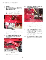
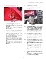
2.5.
With the deck on the ground, the lift rods can be
reconnected to the lift links. This will enable the
rods and links to be moved out of the way by lift-
ing the deck height lever. See Figure 2.5.
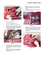
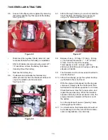
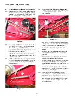
2.6.
Working from the right side of the tractor,
remove the hairpin clip that secures the PTO
cable housing to the bracket on the deck. Sepa-
rate the cable from the bracket. See Figure 2.6.
NOTE:
There is a small plastic spacer that fits
between the hairpin clip and the bracket
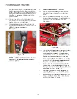
2.7.
Unhook the PTO cable spring from the idler pul-
ley bracket, and move the cable out of the way.
NOTE:
Some early production units were
equipped with a brake rod that passed above the
PTO cable spring. On these models it is neces-
sary to disconnect the brake rod before remov-
ing the spring.
Figure 2.3
Contact point
Belt keeper
Figure 2.4
New locking hairpin clips
secure lift rods to lift links
and cutting deck
Figure 2.5
Lift rod reconnected
Figure 2.6
PTO Cable
Bracket
Hairpin clip
Summary of Contents for 700 Series
Page 2: ......
Page 4: ......
Page 50: ...700 SERIES LAWN TRACTORS 46 ...
Page 52: ...700 SERIES LAWN TRACTORS 48 ...


