background image

700 SERIES LAWN TRACTORS

26

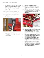
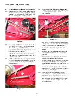
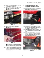
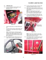
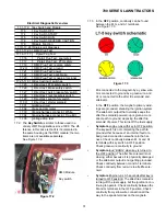
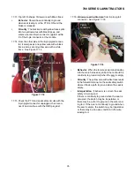
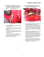
15.7. From this point, the steering shaft may be lifted 

slightly to remove the hex bushing that locates it. 
See Figure 15.7.

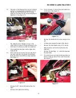
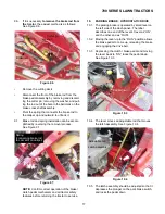
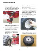
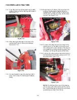
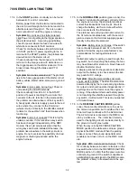
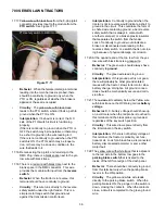
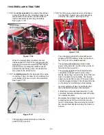
15.8. If the steering shaft support is removed, the 

steering shaft may be removed completely.       
See Figure 15.8.

15.9. It is also feasible to leave the steering shaft in 

place, and remove the steering gear indepen-
dently.

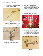
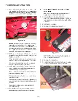
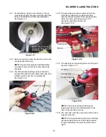
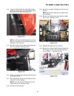
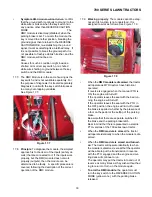
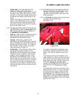
15.10.Depending on the nature of the repair that is to 

be done, and the engine that the tractor is 
equipped with, it may be easier to remove the 
steering arm and drag link along with the steer-
ing gear. See Figure 15.10.

15.11. To remove the drag link prior to removal of the 

steering gear, it is necessary to block the gear 
from turning as the nut is loosened. This may be 
accomplished by holding the steering shaft or by 
inserting a pin through the gear and the frame.

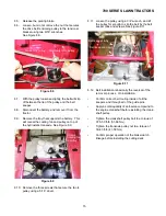
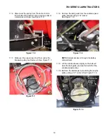
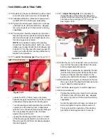
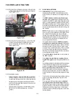
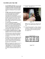
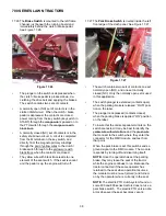
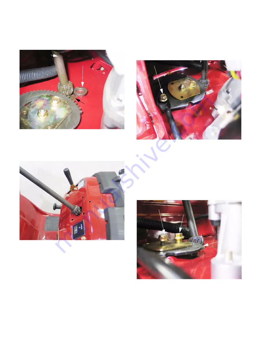
15.12.To remove the steering gear, loosen and remove 

both bolts that hold it in place using a pair of 1/2” 
wrenches. See Figure 15.12.

NOTE: 

The bolt near the center of the steering 

gear comes-up from the bottom, with the nut on 
top. The bolt that passes through the curved slot 
(guide bolt) goes down from the top.

Figure 15.7

Steering shaft
(partially removed)

Steering shaft


hex bushing
(removed from hole)

Hexagonal extrusion
(hole) to locate 
bushing

Figure 15.8

Figure 15.10

Disconnect here...if accessible

Figure 15.12

Steering 
gear

Nut on center bolt

Guide bolt

Summary of Contents for 700 Series

Page 1: ... the product s Oper ators Manual supplied with the equipment No liability can be accepted for any inaccuracies or omission in this publication although care has been taken to make it as complete and accurate as possible at the time of publication However due to the variety of outdoor power equipment and continuing product changes that occur over time updates will be made to these instructions from...

Page 2: ......

Page 3: ...Drive 14 Clutch Brake Linkage Hydrostatic 16 Parking Brake Hydrostatic Drive 17 Belt Replacement Variable Speed Belt Drive 18 Speed Control Linkage Adjustment Variable Speed Belt Drive 20 Cruise Control Parking Brake Adjustment Variable Speed Belt Drive 21 Steering 22 Steering Gear 25 Pivot Bar 28 Electrical System 30 Fastener Installation Specs 47 TABLE OF CONTENTS ...

Page 4: ......

Page 5: ...e steel dash panel is common to all 700 series and plastic inserts will be used to match the different hoods used 1 6 Spotter s Guide The 700 series is visibly simi lar to the existing step through platform 600 and 610 series lawn tractors but there are substan tial differences Drive System Hydro The 790 series de clutches the traction drive belt when the clutch brake pedal is depressed without mo...

Page 6: ...d to the lift links This will enable the rods and links to be moved out of the way by lift ing the deck height lever See Figure 2 5 2 6 Working from the right side of the tractor remove the hairpin clip that secures the PTO cable housing to the bracket on the deck Sepa rate the cable from the bracket See Figure 2 6 NOTE There is a small plastic spacer that fits between the hairpin clip and the bra...

Page 7: ... deck lift links Figure 2 9 Left side slot Cold headed end 3 DECK DETAILS AND UPDATES FOR 2005 3 1 The front deck support rod is easily removed by slipping it forward until the coined spot slips through the opening in the bracket that supports it See Figure 3 1 The nut and jam nut are used to make and secure fore aft deck level adjustment using a pair of 3 4 wrenches The deck should be set slightl...

Page 8: ...it of 5 16 fuel line as a damper See Figure 3 3 3 4 The blade brake pads are attached at a slight angle to prevent chatter on PTO disengagement 3 5 The 42 deck has a fixed idler pulley to provide better wrap on the left spindle pulley and a ten sioner pulley to tighten the belt See Figure 3 5 3 6 The 38 deck has a shorter belt and a single tensioner pulley to tighten the belt See Figure 3 6 Figure...

Page 9: ... Figure 4 1 Deck engagement lever Figure 4 3 Barbed end Hook tool Z Fitting 4 4 The bushing is easily replaced by simply unbolt ing the two halves using a 3 8 wrench See Figure 4 4 NOTE The washer and hairpin clip have been removed here for the sake of visibility NOTE The lever itself is difficult to replace with out removing the fender 4 5 The cable is properly routed behind the trans mission to ...

Page 10: ...and orientation 5 4 The bushings that support the lift shaft assembly are easily replaced See Figure 5 4 Remove the cutting deck or support it using 2 X4 dimensional lumber or similar to relieve the weight from the linkages Lift and safely support the back of the tractor Remove the rear wheels using a 1 2 wrench not absolutely necessary but eases access Remove the E clips from the shaft and replac...

Page 11: ...lift rods are interchangeable left to right but it is important to maintain the correct orientation Figure 5 6 The old blow gun trick Figure 5 7 Unbolt transaxle control linkage here NOTE The stepped bow in the middle goes outboard riding against the transaxle control brackets 5 9 Remove the bushings that support the lift shaft assembly See Figure 5 9 NOTE Use care not to damage the cooling fan wh...

Page 12: ...e lift rod can be removed See Figure 5 13 5 14 Once the lift rods are removed the lift shaft can be withdrawn complete with the lift lever out the opening beneath the left fender See Figure 5 14 5 15 On the bench the lift lever can be rotated in its mounting hole in the lift shaft assembly to relieve the torsion spring tension and align the coined ears on the lever with the notches in the bracket ...

Page 13: ...ped 790 series See Figure 6 1 6 2 If a warrantable problem occurs in the first two years of service the transaxle will be replaced as a unit by an authorized White dealer return ing the transaxle to MTD for vendor recovery It may also be repaired by a Hydro Gear autho rized MTD dealer under the Hydro Gear war ranty 6 3 If any non warranty hydrostatic transaxle ser vice is required it can be perfor...

Page 14: ...ould be 1 1 25 2 54cm 3 18cm from the top of the housing Total capacity is 600 632 gal 2271ml 2391ml of 20W 50 motor oil having an API clas sification of SH CD 6 9 The transaxle must be removed and inverted to drain the fluid out 6 10 After a fluid change purge the system and top up the fluid to the correct level With the engine at idle speed and the by pass valve open slowly cycle the control lev...

Page 15: ...eration and sluggish performance In addition to these symptoms the brake will become extremely hot and the rotor will become discolored Figure 6 12 By pass valve Brake rotor Brake caliper 6 13 The brake rod pulls on a spring that is hooked to the cam arm on the brake caliper The cam arm forces two pins inward against a backing plate and brake pad The pad forces the floating rotor against a second ...

Page 16: ... lever rotates a cross shaft and bellcrank An adjustable rod connects the bellcrank to the input arm on the left side of the transaxle See Figure 7 2 7 3 The input arm on the transaxle will return to neu tral when the rod is disconnected The rod length should be adjusted so that the neutral position of the control lever on the fender corre sponds with neutral position of the input arm If mis adjus...

Page 17: ...tic hex bushings that support the cross shaft are easily replaced See Figure 7 5 Remove the E clip and flat washer from the shaft Remove and replace the bushing Figure 7 4 Bracket bolts Adjustment Figure 7 5 Hex bushing Flat washer E ring Cross shaft Fan 7 6 If it is necessary to remove the cross shaft and control lever See Figure 7 6 Remove the handle from the lever using a blow gun Lift and safe...

Page 18: ...moving the cutting deck and the front deck sta bilizer link The procedure in the operator s manual or the procedure described in the DECK REMOVAL section of this manual will provide some guidance if necessary 8 2 Set the Parking Brake 8 3 Remove the crankshaft pulley using a 5 8 wrench See Figure 8 3 8 4 Pulley Hardware The pulley is secured by a bolt lock washer and a heavy flat washer A spacer i...

Page 19: ...gure 8 6 Stationary idler pulley Tensioning pulley Figure 8 9 Screws holding fan to pulley 8 11 Loosen the pulley using a 3 4 wrench and lift the pulley far enough to slip the belt by the belt keeper tabs and screws See Figure 8 11 8 12 Belt installation is basically the reversal of the removal process On installation Confirm correct belt routing inside of all the keepers and through all of the gu...

Page 20: ... ple and the parts are easy to reach See Figure 9 4 NOTE This procedure may be necessary if the pedal assembly cross shaft or the pedal support brackets exhibit wear after extended use Remove the cutting deck to gain access to the linkage Mark or make note of the linkage connections and orientations relative to the brake pedal assembly Disconnect the extension spring that reaches forward from the ...

Page 21: ...y features before returning the tractor to service Figure 9 6 Brake rod Cotter pin Washer Figure 9 7 Spring connecting brake rod to cam arm on caliper 10 PARKING BRAKE HYDROSTATIC DRIVE 10 1 The parking brake is operated by small lever on the left side of the dash panel The label describes one end of the lever s travel as ON and the other end as RUN 10 2 Moving the lever up to the RUN position all...

Page 22: ...latch for binding or interference Some of the clearances between the latch and the frame are fairly close Component wear with years of use may allow the latch to bind Interference binding will likely be evidenced by wear marks in the metal and paint at the point of contact Replace any visibly worn components and adjust the linkage 10 9 Confirm the correct operation of the tractor s safety features...

Page 23: ...or bolt Nuts Figure 11 7 11 8 Remove the belt guide from the variable speed pulley bracket using a 1 4 socket See Figure 11 8 NOTE Easiest access is through the battery compartment 11 9 Lift the middle sheave slightly so the belt will clear the belt guide and slip the belt off of the variable speed pulley 11 10 Remove the beltkeeper surrounding the engine pulley using a 1 2 wrench See Figure 11 10...

Page 24: ...e installing the crank shaft pulley Tighten the crankshaft pulley bolt to a torque of 37 5 50 ft lb 51 68 Nm Tighten the transaxle pulley nut to a torque of 10 15 ft lb 13 6 20 3 Nm Confirm proper operation of the brake clutch linkage before installing the cutting deck Adjust the speed control linkage if necessary Confirm proper operation of tractor safety fea tures before returning the tractor to...

Page 25: ...st fits into the hole without interfer ence from the bracket Figure 12 3 Adjustment Ferrule Figure 12 4 13 CRUISE CONTROL PARKING BRAKE ADJUSTMENT VARIABLE SPEED BELT DRIVE 13 1 Set the parking brake to expose the adjustment ferrule and cotter pin See Figure 13 1 13 2 Remove and discard the cotter pin that secures the ferrule in the latch assembly then disconnect the linkage from the latch assembl...

Page 26: ...wheel bearings inspect the wheel bearings and axle bushings See Figure 14 3 14 4 The wheel bearings may be easily examined for play Safely lift and support the end of the pivot bar that the wheel is attached to Attempt to wiggle the wheel on a horizontal axis Excessive play indicates worn wheel bearings Rocking play as distinguished from just slipping in and out on the axle that exceeds the range ...

Page 27: ... 14 9 Single use push cap 14 10 The right side axle can be removed from the pivot bar by loosening the clamp bolt that secures the steering arm to the square section at the top of the axle using a pair of 1 2 wrenches and lifting the arm off See Figure 14 10 14 11 The bushings can be easily pried out of the pivot bar See Figure 14 11 NOTE The ends of the axle bushings are tapered to seat into the ...

Page 28: ...lot viewing the steering gear from above 12 teeth of the steering gear should be on each side of the pinion gear tooth that most deeply engages the steering gear 14 18 To adjust the drag link it is necessary to loosen the jam nut that locks the ball joint in position Hold the ball joint using a 1 2 wrench and loosen the nut using an 11 16 wrench See Figure 14 18 14 19 After the jam nut is loosened...

Page 29: ...emove the steering wheel remove the bolt and belleville washer using a 1 2 wrench 15 4 Match mark the steering wheel to the shaft and lift the steering wheel off of the splined end of the steering shaft NOTE The steering wheel need not be removed to remove the steering shaft pinion gear but the steering shaft support must be 15 5 To remove the steering shaft support take out the three screws that ...

Page 30: ... remove the drag link prior to removal of the steering gear it is necessary to block the gear from turning as the nut is loosened This may be accomplished by holding the steering shaft or by inserting a pin through the gear and the frame 15 12 To remove the steering gear loosen and remove both bolts that hold it in place using a pair of 1 2 wrenches See Figure 15 12 NOTE The bolt near the center o...

Page 31: ...ering gear and the drag link One side of the bushing is a flat shoulder the other side is tapered and barbed The flat shoulder faces the gear when installed correctly 15 18 Assembly notes Replace any locking fasteners that show signs of wear or reduced locking function In some cases the parts may be thoroughly cleaned and locked with re leasable thread locking compound such as Loctite 242 blue Rep...

Page 32: ...ng gear pivot bolt should be tightened to a torque of 200 260 in lb 22 6 29 4 Nm The ball joint nuts should be tightened to a torque of 150 250 in lb 17 28 Nm after removal or adjustment 15 19 Thoroughly test the steering before returning the tractor to service Test for ease and freedom of movement Check for loose operation or hardware Turn to full lock in both directions to check link age travel ...

Page 33: ...he frame to allow removal of the front wheels NOTE Do not use the pivot bar as a means to suspend the front of the lawn tractor 16 8 Remove the front wheels Figure 16 4 Spacer 3 8 bolt head Figure 16 5 1 2 Wrenches 16 9 Remove the cotter pins that secure the tie rod to the axle NOTE Discard the cotter pins and replace with new hardware 16 10 Remove the muffler heat shield and the muffler as one un...

Page 34: ...es like NAPA for under 30 00 Appropriate multi meters can be purchased for under 100 00 and are an invaluable tool for any competent technician It is typical when industries shift from electro mechanical to electronic controls that diagno sis shifts from tracing through a number of inde pendent circuits to checking the in puts to and out puts from a central processor This is similar to but much le...

Page 35: ...FF position continuity can be found between the M G and A1 terminals See Figure 17 3 M is connected to the magneto by a yellow wire G is connected to ground by a green wire and A1 is connected to the after fire solenoid and alternator In the OFF position the magneto primary wind ings are grounded disabling the ignition system The alternator output that normally keeps the after fire solenoid powere...

Page 36: ... have continuity Once the engine is running the alternator produces current that tracks back from the A1 circuit to charge the battery via the red wire with white trace connected to the B terminal The plain red wire carrying alternator current to the A1 terminal doubles back with the second plain red wire on that terminal supplying power directly to the after fire solenoid Symptom Battery does not...

Page 37: ...re is covered following the description of the correct operation of the RMC module Figure 17 7 17 9 Working properly The module cannot be diag nosed if its function is not understood It is designed to work as follows See Figure 17 9 When the RMC module is disarmed the tractor will operate as MTD tractors have historical operated If reverse is engaged when the manual PTO is ON the engine will turn ...

Page 38: ...a faulty RMC module If the RMC module does not function as described the RMC plug test should be the first step in diagnosis If the RMC plug test confirms that the safety cir cuits inputs work as designed yet the RMC module does not work properly the RMC mod ule is faulty The RMC plug test will give an indication of what the problem is if it is not a faulty RMC module If the problem is identified ...

Page 39: ...he RMC plug test Figure 17 14 Module connector Pigtail connector 17 16 Yellow wire with white trace from 8 pin pigtail connector See Figure 17 16 Behavior When the female pin terminal leading into the main harness is probed there should be continuity to ground only when the seat is empty Circuitry The yellow wire with white trace leads to the forward terminal on the seat safety switch where it fin...

Page 40: ...ther metal part or a broken plastic insulator that separates the switch from the fender Lack of continuity to ground would indicate a broken or disconnected wire leading to the reverse safety switch or a switch that is not clos ing because of physical damage or corrosion 17 20 At the opposite end of the top row from the yel low wire with black trace is a green wire Behavior The green wire should a...

Page 41: ...een A2 and L in the REVERSE CAUTION MODE position confirm that the green wire connecting to the L terminal does have good continuity to ground and check for any loss of continuity in the white wire that extends from the key switch to the RMC module including the molded connector between the two components 17 24 If the RMC plug test or the pigtail plug test indi cates fault with any of the safety s...

Page 42: ...t front edge of the dash panel See Figure 17 27 The switch contains two sets of contacts one set normally open NO and one set normally closed NC Only the normally open set is used in this application The switch plunger is extended contacts open when the parking brake is released RUN posi tion on the label The plunger is depressed contacts closed when the parking brake is applied ON position on the...

Page 43: ...o the seat mounting bracket See Figure 17 29 The yellow wire with white trace is connected to the front spade terminal on the seat safety switch When the seat is vacant the tab on the seat bracket closes a ground path in series with the PTO switch If the PTO is ON and the seat is empty the circuit is completed shorting out the primary windings of the magneto turning off the engine The yellow wire ...

Page 44: ...ower picked up from the battery cable connection to the hot post of the starter solenoid The red wire with white trace carries fused power to the ammeter and from there to the B terminal on the key switch The ammeter leads both have female spade connectors at the ammeter but are male female where they connect to the rest of the har ness to maintain correct polarity The female spade connector that ...

Page 45: ...ifica tions to test starting and charging systems Figure 17 33 To after fire solenoid To magneto Lighting circuit power Main alternator lead 17 34 The engine harness connector on the Briggs and Stratton powered Troy Bilt tractor also contains alternator and safety circuit components See Figure 17 34 The gray wire in the engine harness leads to the after fire solenoid It receives power from the bat...

Page 46: ...nections physical damage or corrosion 17 38 As a point of illustration a short length of 12 or 14 gauge stranded wire can be stripped at the ends to facilitate an Ohm read ing See Figure 17 38 17 39 For comparison strip away insulation at the mid dle of the wire and snip strands until only a few remain Repeat the Ohm reading There will not be a substantial change See Figure 17 39 While the actual ...

Page 47: ...e negative battery post Voltage drop on a good circuit should be less than 0 1 volts A voltage drop reading on the meter of greater than 0 2 volts indicates a fairly substantial problem that demands attention Figure 17 41 17 42 As an example if the starter solenoid does not engage properly check for voltage drop between the ground point for the starter solenoid and the negative post on the battery...

Page 48: ...p reading on the meter of greater than 0 2 volts indicates a fairly substantial problem that demands attention 17 49 As an example if the tractor had a slow turning starter the ground side voltage drop measured below 0 1 volts and there was not a parasitic load on the engine e g PTO clutch that is not fully disengaged it would be logical for the tech nician to check voltage drop to the starter See...

Page 49: ...than 0 2 Ω through the contacts 17 54 On MTD switches Normally Closed contacts are identified by the letters NC stamped on the spades that connect to those contacts Paired spades going to the same set of con tacts are next to each other flat to flat not edge to edge It is good to test switch contacts in both modes open and closed confirming that each set of contacts is neither shorted nor faulted ...

Page 50: ...700 SERIES LAWN TRACTORS 46 ...

Page 51: ...ering Wheel Screw 17 20 ft lbs 23 27 Nm Chute Mounting Screws 50 100 in lbs 6 11 Nm Idler Pulley 40 50 Ft lbs 55 68 Nm Idler Bracket Pivot Blot 40 50 Ft lbs 55 68 Nm Spindle screws 200 300 in lbs 23 34 Nm Engine Bolts 200 450 in lbs 23 51Nm Trans Axle single speed Transmission Pulley Nut 10 15 ft lbs 14 21 Nm V Speed Bracket 260 350 in lbs 29 40 Nm Tension Pulley 260 350 in lbs 29 40 Nm Perimeter ...

Page 52: ...700 SERIES LAWN TRACTORS 48 ...

Reviews: