PAGE 23
FOR SERVICE TECHNICIAN’S USE ONLY
DO NOT REMOVE OR DES
TROY
DRYER DISASSEMBLY INSTRUCTIONS
Remove Top Panel
1. Unplug dryer or disconnect power.
2. Remove the three rear screws securing
the top panel and extension bracket to the
back panel.
3. Slide the top panel/extension bracket
back to remove.
4. Reverse procedure to reassemble.
Remove Rear Panel (Figure 24)
1. Perform “Remove Top Panel”.
2. ELECTRIC: Remove the cover plate and
disconnect the power cord from the terminal
block and ground screw.
GAS: Remove the cover plate and disconnect
the AC power cord from the ground screw.
3. Remove the two screws securing the
terminal block to rear panel.
4. Remove the 13 screws securing the rear
panel to the cabinet. Remove rear panel from
dryer.
NOTE: The spring clip has been replaced by a
lint duct collar that is secured to the rear panel.
Care must be taken when sliding the panel off
the exhaust outlet because of the tight fit.
5. Reverse procedure to reassemble.
Remove Console, Front Panel,
Front Bulkhead, and Drum
NOTE: Sections A, B, C, and D must be
performed in order.
A: Remove Console (Figure 25)
1. Perform “Remove Top Panel”.
2. Disconnect the drum light harness at
the inline connector as shown in figure 25.
3. Disconnect the CCU to UI harness at the
inline connection as shown in figure 25.
4. Remove the two top screws (closest
to the front) securing console to mounting
bracket.
5. Slide the console up and off the mounting
bracket while feeding the CCU to UI and drum
light harnesses through the opening in the
bracket. Remove console and harnesses
from dryer.
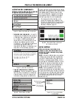
Figure 24 - Remove rear panel.
CCU to UI Connector
Door Switch Connector
Lint Duct Collar
Water Inlet
Ground Screw
Terminal Block
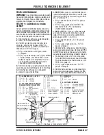
Figure 25 - Remove console.
Console screw (right side shown)
Drum Light
Connector

