2-11
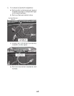
5. Use 3/8" nut driver to connect the neutral
(white) wire to the center terminal block
post with one of the 10–32 hex nuts.
A. 10–32 hex nut
B. Ground-link screw
C. Line 1 (black)
D. Green ground wire
E. Neutral (center) wire
F. Line 2 (red)
A
B
C
F
D
E
6. Connect line 1 (black) and line 2 (red) wires
to the outer terminal block posts with 10-32
hex nuts.
7. Securely tighten hex nuts.
NOTE:
For power supply cord replacement, only
use a power cord rated at 250 volts minimum,
40 amps or 50 amps that is marked for use
with nominal 3/8" (3.5 cm) diameter connec-
tion opening, with ring terminals and marked
for use with ranges.
8. Replace terminal block access cover.
3-wire connection: Power Supply Cord
Use this method only if local codes permit con-
necting chassis ground conductor to neutral
wire of power supply cord.
A. Terminal block
B. Ground-link screw
C. Cord/conduit plate
D. Power supply cord wires
E. Strain Relief
A
B
C
D
E
1. Feed the power supply cord through the
opening in the cord/conduit plate on bot-
tom of range. Allow enough slack to easily
attach the wiring to the terminal block.
2. Use 3/8" nut driver to connect the neutral
(white) wire to the center terminal block post
with one of the 10–32 hex nuts.
A. 10–32 hex nut
B. Line 1 (black)
C. Ground-link screw
D. Neutral (white) wire
E. Line 2 (red)
A
B
C
D
E
Summary of Contents for RY160LXTQ
Page 26: ...2 18 NOTES ...
Page 52: ...5 6 NOTES ...
Page 58: ...6 6 NOTES ...
Page 59: ...7 1 WIRING DIAGRAMS ...
Page 60: ...7 2 ...
Page 62: ......


