


7
Electrical Requirements
IMPORTANT:
The range must be electrically grounded in
accordance with local codes and ordinances, or in the absence
of local codes, with the National Electrical Code, ANSI/NFPA 70
or Canadian Electrical Code, CSA C22.1.
This range is equipped with an electronic ignition system that will
not operate properly if plugged into an outlet that is not properly
polarized.
If codes permit and a separate ground wire is used, it is
recommended that a qualified electrical installer determine that
the ground path is adequate.
A copy of the above code standards can be obtained from:
National Fire Protection Association
1 Batterymarch Park
Quincy, MA 02169-7471
CSA International
8501 East Pleasant Valley Road
Cleveland, OH 44131-5575
■
A 120 V, 60 Hz, AC only, 15 A fused, ground and polarized
electrical circuit is required. A time-delay fuse or circuit
breaker is also recommended. It is recommended that a
separate circuit serving only this range be provided.
■
Electronic ignition systems operate within wide voltage limits,
but proper grounding and polarity are necessary. Check that
the outlet provides 120 V power and is correctly grounded.
■
This gas range is not required to be plugged into a GFCI
(Ground-Fault Circuit Interrupter) outlet. It is recommended
that you not plug an electric spark ignition gas range or any
other major appliance into a GFCI wall outlet as it may cause
the GFCI to trip during normal cycling.
■
Performance of this range will not be affected if operated
on a GFCI-protected circuit. However, occasional nuisance
tripping of the GFCI breaker is possible due to the normal
operating nature of electronic gas ranges.
■
The tech sheet and wiring diagram are located on the back
of the range in a plastic bag.
NOTE:
The metal chassis of the range must be grounded in
order for the control panel to work. If the metal chassis of the
range is not grounded, no keypads will operate. Check with
a qualified electrician if you are in doubt as to whether the
metal chassis of the range is grounded.
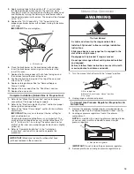
Electrical Shock Hazard
Plug into a grounded 3 prong outlet.
Do not remove ground prong.
Do not use an adapter.
Do not use an extension cord.
Failure to follow these instructions can result in death,
fire, or electrical shock.
WARNING
Gas Supply Requirements
Observe all governing codes and ordinances.
IMPORTANT:
This installation must conform with all local codes
and ordinances. In the absence of local codes, installation must
conform with American National Standard, National Fuel Gas
Code ANSI Z223.1 - latest edition or CAN/CGA B149 -
latest edition.
IMPORTANT:
Leak testing of the range must be conducted
according to the manufacturer’s instructions.
Type of Gas
Natural Gas:
■
This range is factory set for use with Natural gas. See “Gas
Conversions” section. The model/serial/rating plate located
on the oven frame behind the top right-hand side of the oven
door has information on the types of gas that can be used. If
the types of gas listed do not include the type of gas available,
check with the local gas supplier.
Propane Gas Conversion:
Conversion must be done by a qualified service technician.
No attempt shall be made to convert the appliance from the gas
specified on the model/serial/rating plate for use with a different
gas without consulting the serving gas supplier. See “Gas
Conversions” section.
Gas Supply Line
■
Provide a gas supply line of 3/4" (1.9 cm) rigid pipe to the
range location. A smaller size pipe on longer runs may
result in insufficient gas supply. With propane gas, piping or
tubing size can be 1/2" (1.3 cm) minimum. Usually, propane
gas suppliers determine the size and materials used in the
system.
NOTE:
Pipe-joint compounds that resist the action of
propane gas must be used. Do not use TEFLON
®†
tape.
WARNING
Explosion Hazard
Use a new CSA International approved gas supply line.
Install a shut-off valve.
Securely tighten all gas connections.
If connected to propane, have a qualified person make
sure gas pressure does not exceed 14" (36 cm) water
column.
Examples of a qualified person include:
licensed heating personnel,
authorized gas company personnel, and
authorized service personnel.
Failure to do so can result in death, explosion, or fire.
†
®
TEFLON is a registered trademark of Chemours.


