


9
INSTALLATION INSTRUCTIONS
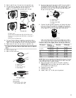
Unpack Range
1.
Remove shipping materials, tape and film from the range.
Keep cardboard bottom under range. Do not dispose of
anything until the installation is complete.
2.
Remove oven racks and parts package from oven and
shipping materials.
3.
To remove cardboard bottom, first take 4 cardboard
corners from the carton. Stack one cardboard corner on
top of another. Repeat with the other 2 corners. Place them
lengthwise on the floor behind the range to support the
range when it is laid on its back.
4.
Using 2 or more people, firmly grasp the range and gently
lay it on its back on the cardboard corners.
5.
Remove cardboard bottom.
The leveling legs can be adjusted while the range is on its back.
See the “Adjust Leveling Legs” section.
NOTE:
To place range back up into a standing position, put a
sheet of cardboard or hardboard on the floor in front of range to
protect the flooring. Using 2 or more people, stand range back
up onto the cardboard or hardboard.
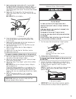
WARNING
Excess
i
ve We
i
ght Hazard
Use two or more people to move and
i
nstall range
.
Fa
i
lure to do so can result
i
n back or other
i
njury
.
Install Anti-Tip Bracket
1.
Remove the anti-tip bracket from the inside of the oven.
2.
Determine which mounting method to use: floor or wall.
If you have a stone or masonry floor, you can use the wall
mounting method. If you are installing the range in a mobile
home, you must secure the range to the floor.
This anti-tip bracket and screws can be used with wood
or metal studs.
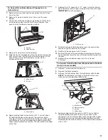
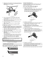
3.
Determine and mark centerline of the cutout space. The
mounting bracket can be installed on either the left-hand or
right-hand side of the cutout. Position mounting bracket
against the wall in the cutout so that the V-notch of the
bracket is 12½" (31.8 cm) from centerline, as shown.
WARNING
T
i
p Over Hazard
A ch
i
ld or adult can t
i
p the range and be k
i
lled
.
Install ant
i
-t
i
p bracket to floor or wall per
i
nstallat
i
on
i
nstruct
i
ons
.
Sl
i
de range back so rear range foot
i
s engaged
i
n the
slot of the ant
i
-t
i
p bracket
.
Re-engage ant
i
-t
i
p bracket
i
f range
i
s moved
.
Do not operate range w
i
thout ant
i
-t
i
p bracket
i
nstalled
and engaged
.
Fa
i
lure to follow these
i
nstruct
i
ons can result
i
n death
or ser
i
ous burns to ch
i
ldren and adults
.
Centerline
A
B
A. 12½" (31.8 cm)
B. Bracket V-notch


