background image

For Service Technician Use Only

COMPONENT TESTING (Cont.)

3-2  

n


Low Profile Microwave Hood Combination

Safety

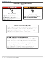
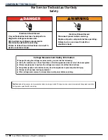
DANGER

Electrical Shock Hazard

Only authorized technicians should perform 

diagnostic voltage measurements.
After performing voltage measurements, 

disconnect power before servicing.
Failure to follow these instructions can result in 

death or electrical shock.

WARNING

Electrical Shock Hazard

Disconnect power before servicing.

Failure to do so can result in death or

electrical shock.

Replace all parts and panels before operating.

Voltage Measurement Safety Information

When performing live voltage measurements, you must do the following:

■  

Verify the controls are in the off position so that the appliance does not start when energized.

■  

Allow enough space to perform the voltage measurements without obstructions.

■  

Keep other people a safe distance away from the appliance to prevent potential injury.

■  

Always use the proper testing equipment.

■  

After voltage measurements, always disconnect power before servicing.

Caution

: Label all wires prior to disconnection when servicing controls. Wiring errors can cause improper and dangerous operation.


Verify proper operation after servicing.

Summary of Contents for KMLS311HBL

Page 1: ...SERVICE MANUAL Low Profile Microwave Hood Combination W11387992B Multimedia Enhanced ...

Page 2: ...viced refer to the Use and Care Guide or Installation Instructions provided with the oven GOALS AND OBJECTIVES The goal of this Service Manual is to provide information that will enable the In Home Service Professional to properly diagnose malfunctions and repair the Low Profile Microwave Hood Combination The objectives of this Service Manual are to Understand and follow proper safety precautions ...

Page 3: ... 1 10 SECTION 2 DIAGNOSTICS 2 01 SAFETY 2 02 DIAGNOSTICS TOUCH PANEL 2 03 ERROR FAILURE CODES INDICATIONS 2 04 SECTION 3 COMPONENT TESTING 3 01 SAFETY 3 02 WIRING DIAGRAM 3 03 COMPONENT TESTING 3 07 COMPONENT LOCATION NOT TO SCALE 3 10 SECTION 4 COMPONENT ACCESS 4 01 ACCESSING THE CONTROL PANEL 4 02 DOOR REMOVAL 4 03 OUTER WRAPPER REMOVAL 4 04 COMPONENT LOCATIONS 4 04 COOKTOP FAN AND LIGHT BOARD A...

Page 4: ...iv n Low Profile Microwave Hood Combination NOTES ...

Page 5: ...1 Section 1 General Information This section provides general safety parts and information for the Low Profile Microwave Hood Combination Microwave Hood Combination Safety Product Specifications Model and Serial Label Location Model Nomenclature Tech Sheet Location ...

Page 6: ...ers All safety messages will follow the safety alert symbol and either the word DANGER or WARNING These words mean follow instructions instructions DANGER WARNING PRECAUTIONS TO AVOID POSSIBLE EXPOSURE TO EXCESSIVE MICROWAVE ENERGY a Do not attempt to operate this oven with the door open since open door operation can result in harmful exposure to microwave energy It is important not to defeat or t...

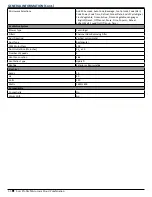
Page 7: ...umber of Racks 0 Work Surface Light Halogen LED Turntable Stoppable Recessed Turntable Diameter Size IN inches 12 Description Microwave Type Over the range Size IN inches 30 Exterior Cabinet Color Black White Stainless Steel Black Stainless Steel Door Swing Left Controls Control Location Right Front Control Type Electronic Touch Display Color White Electronic Display Type LED LCD Number of Keypads...

Page 8: ...s English French Off Cancel Pause Pizza Popcorn Reheat Sound On Off Soup Steam Timer Ventilation System Blower Type Centrifugal Filters Charcoal Odor Removing Filter Duct Direction Vertical or Horizontal Duct Type Rectangular CFM Motor Class 400 Duct Outlet Size IN inches 31 4 x 10 Number of Speeds 3 or 4 Vent Fan Location Side Ventilation Type Updraft Venting Exterior or Recirculating Electrical ...

Page 9: ...r Light LED Number of Racks 0 Work Surface Light LED Turntable Stoppable Recessed Turntable Diameter Size IN inches 12 Description Microwave Type Over the Range Size IN inches 30 Exterior Cabinet Color Black White Stainless Steel Black Stainless Door Swing Left Controls Control Location Right Front Control Type Electronic Touch Display Color White Electronic Display Type LCD Number of Keypads 24 S...

Page 10: ...h French Off Cancel Pause Pizza Popcorn Reheat Soften Melt Sound On Off Soup Timer Ventilation System Blower Type Centrifugal Filters Charcoal Odor Removing Filter Duct Direction Vertical or Horizontal Duct Type Rectangular CFM Motor Class 500 Duct Outlet Size IN inches 31 4 x 10 Number of Speeds 4 Vent Fan Location Side Ventilation Type Updraft Venting Exterior or Recirculating Electrical Amps 15...

Page 11: ...GENERAL INFORMATION Cont Low Profile Microwave Hood Combination n 1 7 Model and Serial Number Location Model Serial Number Label Location behind door ...

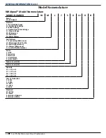
Page 12: ...n Range X Drop In Range M Microwave O Wall Oven N Warm Drawer Sub Platform C Countertop Microwave H Microwave Hood Combo B Built In Microwave D Drawer Microwave L Low Profile Microwave Series 1 OPP 3 Low Line 5 Mid Line 7 High Gold 9 Hero Gold Feature Level 0 9 Feature Level 0 9 Capacity 11 1 1 Cu Ft 17 1 7 Cu Ft 18 1 8 Cu Ft 19 1 9 Cu Ft Year of Production E 2015 F 2016 G 2017 H 2018 J 2019 Stand...

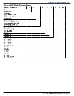
Page 13: ... Oven O Wall Oven S Slide In Range Configuration Fuel C Countertop Microwave H Microwave Hood Combo B Built In Microwave L Low Profile Microwave Product Details S Sensor Cooking C Convection P Speedcook G Grill Feature Pack Feature Pack Capacity 11 1 1 Cu Ft 17 1 7 Cu Ft 18 1 8 Cu Ft 19 1 9 Cu Ft Year of Production E 2015 F 2016 G 2017 H 2018 J 2019 Standard BL Black BS Black Stainless SS Stainles...

Page 14: ...GENERAL INFORMATION 1 10 n Low Profile Microwave Hood Combination Tech Sheet Location Tech Sheet Location on some models On the back of panel ...

Page 15: ...ICS Low Profile Microwave Hood Combination n 2 1 Section 2 Diagnostics This section provides diagnostic and fault codes information for the Low Profile Microwave Hood Combination Safety Diagnostics Error Codes ...

Page 16: ...le a safe distance away from the appliance to prevent potential injury Always use the proper testing equipment After voltage measurements always disconnect power before servicing IMPORTANT Electrostatic Discharge ESD Sensitive Electronics ESD problems are present everywhere ESD may damage or weaken the electronic control assembly The new control assembly may appear to work well after repair is fin...

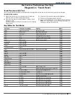
Page 17: ...CU xx xx xx ACU SW version check 1 beep Start UI xx xx xx UI SW version check 1 beep Start LT xx Left touch SW version check 1 beep Start RT xx Right touch SW version check 1 beep Start GEE xx xx xx GEE SW version check 1 beep Hood Light key 03 or 0009 1 beep Hood Fan key 04 or 0011 1 beep Timer key 05 or 0010 1 beep Turntable On Off key 09 1 beep Cook value between 2000 and 9000 Humidity sensor c...

Page 18: ...splay the humidity sensor reading If display does not show the value between 2000 and 9000 continue to Step 2 2 Unplug microwave oven or disconnect power 3 Connect a new humidity sensor ACU to cable 4 Replace all parts and panels before operating 5 Plug in microwave oven or reconnect power 6 Enter the Diagnostics mode press CANCEL CANCEL START then press COOK to see if failure code reappears NOTE ...

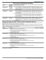
Page 19: ...lace Phoebe ACU Primary Secondary Monitor and Door Switch Checkout Procedures IMPORTANT Before checking the interlock switches unplug microwave oven or disconnect power Be sure to disconnect all of the wires at the switch being tested before making any continuity readings NOTE The Secondary Interlock Switch Monitor Interlock Switch Primary Interlock Switch and Door Interlock Switch are mounted in ...

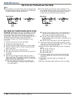
Page 20: ... at the high voltage transformer primary input wires If the voltage is not close to the rating voltage 120 15 VAC unplug microwave oven or disconnect power Check the circuitry as follows Measure resistance of the fuse micro switches and thermostats Replace any failed components Refer to the wiring diagram Check for loose terminals Refer to the wiring diagram Check all of the terminals on the main ...

Page 21: ...J21 1 or J2 1 Use the positive test lead to probe connectors designated below MW Oven Plugged In Sitting Idle ACV Readings MW Oven Running ACV Readings Pin Name Wire Color Power On Door Closed Power On Door Open Hood Fan Motor High Hood Fan Motor Med High Hood Fan Motor Medium Hood Fan Motor Low Hood Light High Hood Light Low Microwave Oven Start P1 1 L BLACK 120 120 120 N A 120 120 120 120 120 P1...

Page 22: ...Reading MW Oven Running ACV Reading Pin Name Wire Color Power On Door Closed Power On Door Open Hood Fan Motor High Hood Fan Motor Low Hood Light Microwave Oven Start J21 1 N WHITE 0 0 0 0 0 0 J21 2 NA N A N A N A N A N A N A N A J21 3 TT RED 0 118 0 0 0 118 J21 4 L BLACK 120 120 120 120 120 118 J2 1 N BLUE 0 0 0 0 0 0 J2 2 HFH BLACK 0 0 120 55 0 0 J2 3 HFL WHITE 0 0 135 120 0 0 J2 4 CL CF RED BLA...

Page 23: ...e Hood Combination n 3 1 Section 3 Component Testing This section provides the wiring diagram component testing and component location for the Low Profile Microwave Hood Combination Safety Wiring Diagram Component Testing Component Location ...

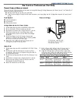
Page 24: ...Replace all parts and panels before operating Voltage Measurement Safety Information When performing live voltage measurements you must do the following Verify the controls are in the off position so that the appliance does not start when energized Allow enough space to perform the voltage measurements without obstructions Keep other people a safe distance away from the appliance to prevent potent...

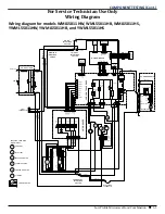
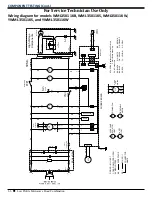
Page 25: ...22 24BR16 01GY28 J2 LHS TOUCH BOARD J2 02GY28 03GY28 04GY28 05GY28 01GY28 02GY28 03GY28 04GY28 05GY28 40GY28 41GY28 42GY28 43GY28 44GY28 HOOD NTC 04RD22 17RD20 HL HF_ML RELAY 4 RELAY 3 RELAY 2 RELAY 1 HLR2 HLR1 GND VRELAY CL CF TTM ODM NFS DOOR 33K 33K 68K SMPS FUSE 1 A VDR ODM RELAY 49XX CL RELAY 4901 MW RELAY 4903 TT RELAY 4902 N RELAY 4 RELAY 3 RELAY 2 RELAY 1 HLR2 HLR1 GND VRELAY HF_M HF_L HF_...

Page 26: ... 5 6 7 HL HF_ML HF_M HF_L HF_H L P14 P15 P4 P5 P8 P1 P2 RELAY 4909 RELAY 4910 RELAY 4917 RELAY 4916 RELAY 4911 RELAY 4912 HLR2 HLR1 GND VRELAY HOOD BOARD HOOD LED CAVITY LED 1 2 3 4 5 6 7 8 1 2 1 2 2 1 3 1 2 1 2 RELAY 4906 GND HL LED2 RELAY 4905 GND GND 12 7 V 3 HL LED1 RELAY 4904 GND CL LED1 1 2 1 2 3 4 65BU22 07WH22 60RD22 P7 1 13GN22 16BK22 27RD22 11BK20 19BU22 12BK20 1 1 2 2 3 1 2 3 3 4 CL CF ...

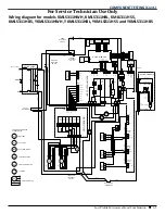
Page 27: ...1 2 65BU22 P7 1 1 2 3 4 38GY22 49BK22 50GY22 29WH22 28BK22 25BK20 21WH22 HL HF_ML HF_M HF_L HF_H L P14 RELAY 4909 RELAY 4910 RELAY 4917 RELAY 4916 RELAY 4911 RELAY 4912 HOOD BOARD 1 2 3 4 5 6 7 P15 HLR2 RELAY 1 RELAY 2 RELAY 3 RELAY 4 HLR1 GND VRELAY 1 2 3 4 5 6 7 8 CR CF TTM ODM 07WH22 13GN22 16BK22 27RD22 11BK20 19BU22 12BK20 MAGNETRON H V TRANSFORMER H V DIODE WHITE TUBE BLACK TUBE BLACK TUBE R...

Page 28: ...erlock Switch Magnetron Thermostat Monitor Interlock Switch Primary Interlock Switch Cavity Thermostat r o t o M r o t i c a p a C F H L C L H D R A O B E B E O H P F C TT Magnetron Red Tube FA F R WH Black Tube Black Tube H V H V Diode Capacitor Transformer H V High Voltage Components 2 J9 J8 OR P32 2 P33 2 BU P32 1 P33 1 OR BU J16 J2 J11 J14 1 K B 1 6 P R O L O C E R I W T 0 6 1 U M O N G W D N ...

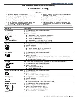
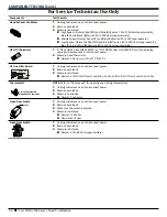
Page 29: ...3 2k ohms approximate Motor Capacitor 1 Unplug microwave oven or disconnect power 2 Remove wire leads 3 Measure resistance Normal Momentarily 0 ohms then goes to Infinite Humidity Sensor PCBA 1 Unplug microwave oven or disconnect power 2 Remove the 4 pin connector from the cable 3 Measure resistance across pins 1 and 2 Normal 10K ohms 5 at 77 F 25 C 4 Measure capacity value across pins 3 and 4 Nor...

Page 30: ...olls on display unplug microwave oven or disconnect power 2 Measure hood thermistor Normal 10 k ohms 5 at 77 F 25 C AC Line Filter Board 1 Unplug microwave oven or disconnect power 2 Remove wire leads 3 Measure resistance Normal L IN to L OUT coil Less than 1 ohm N IN to N OUT coil Less than 1 ohm Thermostats NOTE Refer to Parts Layout for opening and closing temperatures 1 Unplug microwave oven o...

Page 31: ... Make note of the voltage while the microwave oven is running and proceed to the output test Measure Voltage Output Test 1 Fill the measuring cup with 2 cups 500 mL of 70 F 21 C tap water 2 Stir the water with the thermometer to ensure uniform temperature Add warm or cool water to bring the water to the correct temperature 3 Place the measuring cup in the center of the microwave oven cavity 4 Oper...

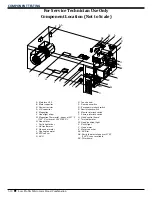
Page 32: ...tron Thermostat opens at 257 F 125 C closes at 203 F 95 C H Hood motor I Cavity light driver J HV transformer K Open door motor L Cooling fan motor M NTC sensor N ACU O Touch panel P Door open switch Q Secondary interlock switch R Door interlock switch S Monitor interlock switch T Primary interlock switch U Hood control board V Turntable motor W Hood cooktop light X Cavity light Y Hood motor Z Mot...

Page 33: ...val and replacement instructions for the Low Profile Microwave Hood Combination Accessing the control panel Door Removal Outer Wrapper Removal Component Locations Cooktop Fan and Light board and Techsheet location Hood motor location Interlock switch replacement Video Available Look for this ICON throughout Section 4 Multimedia Enhanced ...

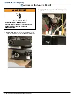
Page 34: ...on the top of the panel then remove the Phillips screw on the top right side of the panel 2 Lift and pull out to access the control and components behind it WARNING Electrical Shock Hazard Disconnect power before servicing Failure to do so can result in death or electrical shock Replace all parts and panels before operating ...

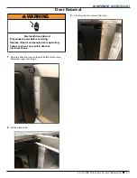
Page 35: ...and remove the small black plastic piece below the upper door hinge 2 Set the piece aside 3 Lift and pull out to remove the door WARNING Electrical Shock Hazard Disconnect power before servicing Failure to do so can result in death or electrical shock Replace all parts and panels before operating ...

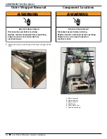
Page 36: ...t power before servicing Failure to do so can result in death or electrical shock Replace all parts and panels before operating WARNING Electrical Shock Hazard Disconnect power before servicing Failure to do so can result in death or electrical shock Replace all parts and panels before operating B A C D E F A Motor Capacitor B Cement Resistor C Main Fuse 20 A D Filter Board E Cavity Light Driver F...

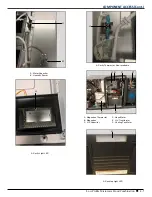
Page 37: ...Combination n 4 5 A B A Motor Capacitor B Humidity Sensor A A Cavity Light LED A A Cavity Thermostat Non resettable B A C D F E A Magnetron Thermostat B Magnetron C H V Capacitor D Hood Motor E H V Transformer F Cooling Fan Motor A A Cooktop Light LED ...

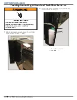
Page 38: ...he two Phillips screws on the right side of the panel 2 Lift and pull out the panel the board and tech sheet are located on the back of the panel WARNING Electrical Shock Hazard Disconnect power before servicing Failure to do so can result in death or electrical shock Replace all parts and panels before operating A B A Cooktop Fan and Light board B Tech sheet ...

Page 39: ...ctrical Shock Hazard Disconnect power before servicing Failure to do so can result in death or electrical shock Replace all parts and panels before operating 1 Remove two Torx screws on the right front of cavity Open the door to access these 2 The control panel must be removed to access the switches after these Torx screws are removed WARNING Electrical Shock Hazard Disconnect power before servici...

Page 40: ... Disconnect wires from the control panel to access the interlock 4 Pull the interlock assembly out to replace switches or assembly 5 When re installing make sure that cam is in this position 6 Move the cam back to this position after the Torx screws have been tightened ...

Page 41: ...Low Profile Microwave Hood Combination n 4 9 NOTES ...

Page 42: ... NUMBER READY TO IDENTIFY YOU AS AN AUTHORIZED IN HOME SERVICE PROFESSIONAL FOR LITERATURE ORDERS CUSTOMER EXPERIENCE CENTER PHONE 1 800 851 4605 FOR TECHNICAL INFORMATION AND SERVICE POINTERS www servicematters com IN CANADA FOR PRODUCT SPECIFICATIONS AND WARRANTY INFORMATION CALL 1 800 461 5681 FOR TECHNICAL ASSISTANCE WHILE AT THE CUSTOMER S HOME CALL THE TECHNICAL ASSISTANCE LINE 1 800 488 479...

Page 43: ......

Reviews: