background image

4

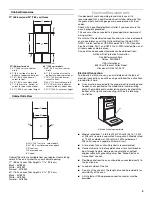
If the house has aluminum wiring follow the procedure below:

1. Connect a section of solid copper wire to the pigtail 

leads.

2. Connect the aluminum wiring to the added section of 

copper wire using special connectors and/or tools 
designed and UL listed for joining copper to aluminum.

Follow the electrical connector manufacturer's recommended 
procedure. Aluminum/copper connection must conform with 
local codes and industry accepted wiring practices.

INSTALLATION INSTRUCTIONS

Prepare Built-In Oven

1. Decide on the final location for the oven. Locate existing 

wiring to avoid drilling into or severing wiring during 
installation. 

2. To avoid floor damage, set the oven onto cardboard prior to 

installation. Do not use handle or any portion of the front 
frame or trim for lifting.
On models with shipping feet attached:

To avoid product damage, do not remove the shipping feet at 
the front lower corners of the oven. The shipping feet will 
protect the lower oven trim until the oven is inserted into 
cabinet.

3. Remove the shipping materials and tape from the oven.
4. Remove the hardware package from inside the bag containing 

literature.

5. Remove and set aside racks and other parts from inside the 

oven.

6. Move oven and cardboard close to the oven’s final location.
7. Open the oven door.
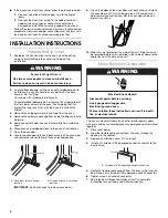
8. Locate the oven door latches in both corners of the oven door, 

and rotate the latches forward to the unlocked position.

IMPORTANT: Use both hands to remove oven doors.

9. Grasp the edges of the oven door with both hands and close 

the oven door until it will no longer close. Lift and pull oven 
door toward you and remove. Set the oven door aside on a 
protective surface.

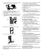
10. Side trims are located on the side of the unit. Side trims must 

be removed before unit is installed in the cabinet. Remove the 
cable ties from the side of the unit.

Make Electrical Connection

This oven is manufactured with a neutral (white) power supply 
wire and a cabinet-connected green (or bare) ground wire twisted 
together.
1. Disconnect power.
2. Feed the flexible cable conduit from the oven through the 

opening in the cabinet. 

3. Remove junction box cover if it is present.
4. Install a UL listed or CSA approved conduit connector to the 

junction box.

5. Route the flexible cable conduit from the oven to the junction 

box through a UL listed or CSA approved conduit connector.

6. Tighten screws on conduit connector.
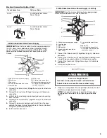
7. See “Electrical Connection Options Chart” to complete 

installation for your type of electrical connection.

A. Oven door latch in locked 

position

B. Oven door latch in unlocked 

position

WARNING

Excessive Weight Hazard

Use two or more people to move and install oven.

Failure to do so can result in back or other injury.

A

B

A. UL listed or CSA approved conduit connector

WARNING

Electrical Shock Hazard

Disconnect power before servicing.

Use 8 gauge solid copper wire.

Electrically ground oven.

Failure to follow these instructions can result in death, 
fire, or electrical shock.

A

Summary of Contents for GMC275PRB00

Page 1: ...four encastré 9 Raccordement électrique 10 Installation du four 11 Achever l installation 12 You can be killed or seriously injured if you don t immediately You can be killed or seriously injured if you don t follow All safety messages will tell you what the potential hazard is tell you how to reduce the chance of injury and tell you what can happen if the instructions are not followed Your safety...

Page 2: ...ensions provide minimum clearance with oven Recessed installation area must provide complete enclosure around the recessed portion of the oven Grounded electrical supply is required See Electrical Requirements section Electrical supply junction box should be located 3 7 6 cm maximum below the support surface when the oven is installed in a wall cabinet A 1 2 5 cm minimum diameter hole should have ...

Page 3: ...connected to the proper electrical voltage and frequency as specified on the model serial number rating plate The model serial number rating plate is located at the bottom of the right hand mounting rail See the following illustration Models rated from 7 3 to 9 6 kW at 240 volts 5 5 to 7 2 kW at 208 volts require a separate 40 amp circuit Models rated at 7 2 kW and below at 240 volts 5 4 kW and be...

Page 4: ...s forward to the unlocked position IMPORTANT Use both hands to remove oven doors 9 Grasp the edges of the oven door with both hands and close the oven door until it will no longer close Lift and pull oven door toward you and remove Set the oven door aside on a protective surface 10 Side trims are located on the side of the unit Side trims must be removed before unit is installed in the cabinet Rem...

Page 5: ...nnect the 2 white wires D and the green or bare ground wire of the oven cable using a UL listed wire connector 3 Connect the 2 red wires G together using a UL listed wire connector 4 Install junction box cover Install Oven 1 Using 2 or more people lift oven partially into cabinet cutout Use the oven opening as an area to grip NOTE Push against seal area of oven front frame when pushing oven into c...

Page 6: ...s 4 For oven use and cleaning read the Use and Care Guide Check Operation of Lower Oven 1 Turn power on PF should appear in the display 2 Press BROIL BROIL will appear in the display 3 Press START Make sure the oven door is closed and the ON light is showing in the display area If oven s does not operate check the following Household fuse is intact and tight or circuit breaker has not tripped Elec...

Page 7: ...t règlements en vigueur Respecter les dimensions indiquées pour la cavité d installation entre les placards Ces dimensions prennent en compte le dégagements de séparation nécessaires L espace d installation doit permettre la formation d une enceinte complète autour de la partie encastrée du four Risque possible de décès ou de blessure grave si vous ne suivez pas immédiatement les instructions Risq...

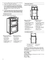
Page 8: ... de la pièce de remplissage pour four de 30 76 2 cm est de 4 12 2 cm Noir 4378944 Blanc 4378945 Amande 4378946 Modèles de 27 68 6 cm A Largeur de l encastrement 25 64 5 cm B Hauteur hors tout 42 107 8 cm C Largeur hors tout 26 67 9 cm D Profondeur de l encastrement 23 58 4 cm max E Hauteur de l encastrement 41 104 1 cm Modèles de 30 76 2 cm A Largeur de l encastrement 28 71 2 cm B Hauteur hors tou...

Page 9: ...aison à la terre Voir la section Raccordement électrique Le câble blindé flexible de l appareil doit être connecté directement dans le boîtier de connexion Installer un fusible pour chaque fil de phase Ne pas couper le conduit La longueur du conduit fournie est destinée à faciliter l entretien du four L installateur doit fournir un connecteur de conduit homologation UL ou CSA Si le domicile est éq...

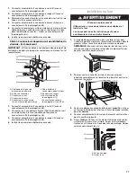
Page 10: ...ecteur de conduit 7 Voir Tableau des options de raccordement électrique pour terminer l installation correspondant à votre type de raccordement électrique Tableau des options de raccordement électrique Câble à 4 conducteurs depuis le point de distribution du domicile IMPORTANT Utiliser le câble à 4 conducteurs provenant du point de distribution du domicile aux États Unis lorsque les codes ne perme...

Page 11: ...plus soulever le four pour l introduire partiellement dans l ouverture d installation dans le placard utiliser l ouverture du four comme zone de prise REMARQUE Pousser contre la zone du joint du four sur le châssis avant pour introduire le four dans le placard Ne pas pousser contre les bords externes 2 Pousser contre la zone du joint du châssis avant pour introduire complètement le four dans le pl...

Page 12: ...e fonctionne nt pas contrôler ce qui suit Les fusibles du domicile sont intacts et serrés le disjoncteur n est pas déclenché La prise de courant est correctement alimentée Voir la section Dépannage dans le Guide d utilisation et d entretien 4 Après 5 minutes de fonctionnement du four évaluer l échauffement au toucher Si aucune chaleur n est ressentie ou si un F apparaît sur l affichage éteindre le...

Reviews: