Page 5
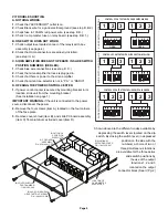
LOCATION OF
6 POSITION
DIP SWITCH
C.
PC BOARD
ASSEMBLY.
P/N 02-0166817-00
LOCATION OF
3 AMP MASTER
SPADE FUSE
D.
ALUMINUM
EXTRUDED COVER.
P/N 11-441328-007
B.
COVER SHROUD.
PART NUMBER
11-661263-000
A.
4-40 X 3/8 INCH PAN
HEAD TAPTIGHT SCREW.
P/N 14-040215-063
1 2 3
1 2 3
1 2
OPEN
3 4 5 6
1 2
OPEN
3 4 5 6
CONTROL OF OUTPUTS WITH SLIDE SWITCH IN RED
SLIDE
SWITCH
IN
POSITION
3
1 2 3
1 2 3
1 2
OPEN
3 4 5 6
1 2
OPEN
3 4 5 6
CONTROL OF OUTPUTS WITH SLIDE SWITCH IN YELLOW
SLIDE
SWITCH
IN
POSITION
2
1 2
OPEN
3 4 5 6
1 2
OPEN
3 4 5 6
1 2 3
1 2 3
CONTROL OF OUTPUTS WITH SLIDE SWITCH IN GREEN
SLIDE
SWITCH
IN
POSITION
1
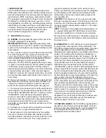
VI.TROUBLE SHOOTING.
A. NOTHING WORKS.
1.
Check that “ACCESSORY” outlet is on.
2.
Check Black wire for a good electrical ground (see step III.B.2.)
3.
Check fuse in 10 AWG red power wire. (see step III.D.)
4.
Check 3 amp master fuse on relay board. (see step III.B.1.)
B. ONE SWITCH DOES NOT WORK.
1.
Check output fuse located on rear of the relay/switch box
assembly (see page 4).
2.
Check that crimp connectors are properly installed.
(see step III. A.)
C. SIREN AMPLIFIER DOES NOT OPERATE IN SLIDE SWITCH
POSITION NUMBER 3 (RED LED).
1.
Check blue wire connections (see step III. C.)
2.
Check that siren amplifier harness is plugged in.
3.
Check that there is power to the siren amplifier.
4.
Check that siren tone selector is not in “P.A.” or “RADIO”.
D. OPENING THE POWER CONTROL CENTER.
1.
If power control center is secured by mounting bracket in its
location, slide unit from the mounting bracket
(See Installation on page 1).
IMPORTANT WARNING.
if the unit is connected to the power
source, disconnect the power.
2.
Remove the four screws (item A), located on the four corners
of the face plate.
3.
Remove cover shroud (item B), and slide PC board assembly
(item C) from aluminum extruded cover (item D).
Shown above are the different modes available by
depressing the switch levers located on the dip
switch. By closing the switch lever (in depressed
position on the side with the
numbers) a choice of two or
three simultaneous functions
are available for the three active
slide switch positions by
the use of the output
functions 1, 2 and 3
located on the output
connector block (See IV,Pg. 2)


