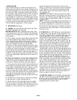
Page 4
I. INTRODUCTION.
The PCC-S9R features a 4 position slide switch and six
SPST push button switches. Five of these switches have 20
amp circuit capability for most primary and secondary warn-
ing functions. A SPST momentary contact switch (Switch
#7, see page 4) compliments the Power Control Center with
the ability to control strobe low power, gun lock, or trunk
lock applications. In addition to controlling primary warning
light functions, the slide switch has an automatic siren-turn-
on feature. This gives the operator true single lever control
over both primary warning lights and siren functions.
The PCC-S9R is designed for a 12V DC system.
II.
MOUNTING
(See page 1).
III. WIRING.
All wiring tasks take place at the rear of the
PCC-S9R relay/switch box assembly.
IMPORTANT NOTE:
Before attempting any wiring, make
sure all switches are in the “OFF” position. The slide switch
must be in the full left position, and all push buttons must be
fully extended.
A.
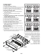
The 12 position output connector block is located on the
rear of the relay/switch box assembly behind the slide
switch. Disregard any number molded into the plastic con-
nector housing. Refer instead to the illustration and refer-
ence chart on page 4 for switch-to-output position
information. The PCC-S9R is supplied with a bag of crimp-
on, push on connectors sized to accept customer supplied
14 AWG wire. Leave enough slack in all these wires to
allow the relay/switch box assembly to be removed from the
mounting bracket (see page 1). Strip wire ends approxi-
mately 1/4” and insert into terminal. Crimp firmly. Insert the
wire into the appropriate output position of the output con-
nector block.
B.
The two wire harness on the rear of the relay/switch box
assembly has a mating two wire connector harness to be
crimped to a customer supplied 2 conductor cable and
wired into the vehicular electrical system (See page 4).
1.
The red wire is the positive feed for all the switches and
indicator lights. This wire should be connected to the vehi-
cle fuse block “ACCESSORY OUTLET”. Failure to use the
“ACCESSORY” outlet will cause the indicator lights to
remain on, and drain the vehicle battery. This circuit is pro-
tected by a 3 amp fuse located on the relay board inside the
relay/switch box assembly. This system master fuse is
accessible by removing the aluminum extruded cover from
the relay board.
2.
The black wire is the ground for all switches and relays.
Connect this wire to a good electrical ground.
C.
Output number 4 in the terminal block is the auxiliary
siren turn-on feature from slide switch position number 3
(red LED indicator). Its purpose, when connected to a siren
amplifier, is to turn on the siren. This output provides a
ground for automatic activation of the electronic siren.
Check your electronic siren owners manual for compatibil-
ity with this feature.The siren tone is determined by the
setting of the siren function control knob located on the
siren amplifier unit.
CAUTION!
If this feature is not to be used, do not make
this wire connection! However, if this feature is to be used,
insert the end of the blue wire assembly with the push on
connector into the output position number 4 on the output
connector block.
NOTE:
The length of the supplied blue wire assembly, 13
in., requires the Models PCC-S9R Power Control Center
and the siren amplifier to be mounted in close proximity.
D.
Connect the 10 AWG red wire to the battery positive ter-
minal. Fuse this circuit at 50 amps as close as possible to
the power source.
IV. OPERATION.
The PCC-S9R uses a 6 pole dip switch
to program the output operation of the slide switch. The
PCC-S9R is shipped with the dip switch levers in the open
position (depressed on the end with the word OPEN),
allowing single output operation in each slide switch active
position. For multiple outlet functions see illustration on
page 3 and programming mode chart on page 5. The dip
switch is located on the relay board of the PCC-S9R (see
page 3 and 5), and is accessible by removing the alumi-
num extruded cover from the relay board (see page 3).
With all electrical connections made, and the vehicle
“ACCESSORY” outlet on, the PCC-S9R will display the fol-
lowing characteristics: The slide switch LED indicators will
be off, and the green LED indicators will be lit behind the
function windows located above the push button switches.
As the slide switch is moved progressively to the right, the
green, yellow, and red LED indicators will turn on in
sequence as well as the corresponding output(s) located
in the output block. As each push button is depressed, the
green indicator back lighting the function window will
change to red and the corresponding output on the output
block will turn on (see page 4 for switch details). Note that
switch number 7 is a momentary contact switch with iso-
lated contacts. The indicator light will show red and the
outlet will remain on only as long as the button is
depressed. This circuit must be fused by a customer sup-
plied one amp fuse. Most likely uses for this switch are
strobe low power, trunk lock, or gun lock.
V. FUNCTION LABELS.
The PCC-S9R is supplied with an
assortment of commonly used function labels. Verify the
function of each push button switch. Peel the labels from
the backing sheet and stick them on the front of the
appropriate switch function window.


