


Page 6
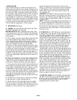
WI
R
I
N
G
D
I
A
G
RA
M F
OR T
H
E PCC
-
S
9
R PO
W
ER CONTRO
L
CENTER
N
ORMALLY OP
EN
20 AMPS (MAX)
@
13
.
5 VDC
F
UNCT
I
ON
N
ORMALLY OP
EN
20 AMPS (MAX)
@
13
.
5 VDC
N
ORMALLY OP
EN
20 AMPS (MAX)
@
13
.
5 VDC
N
ORMALLY OP
EN
20 AMPS (MAX)
@
13
.
5 VDC
N
ORMALLY OP
EN
20 AMPS (MAX)
@
13
.
5 VDC
N
ORMALLY OP
EN
20 AMPS (MAX)
@
13
.
5 VDC
N
ORMALLY OP
EN
20 AMPS (MAX)
@
13
.
5 VDC
N
ORMALLY OP
EN
20 AMPS (MAX)
@
13
.
5 VDC
N
ORMALLY OP
EN
1 AMP (MAX)
N
ORMALLY CLOS
E
D
1 AMP (MAX)
COMMO
N
+
13
.
5VDC ACC
.
S
I
R
EN
O
N.
OP
EN
COL
-
L
E
CTOR 250
m
A (MAX)
N
OT
E:
T
HI
S
F
U
N
CT
I
O
N
ACT
I
VAT
E
S A W
HE
L
EN
WS
-
295MP S
I
R
EN
AMP
.
OUTPUT
1
2
3
4
5
6
7
8
9
10
11
12
ACT
IV
AT
I
ON
SL
I
D
E
SW
I
TC
H
GR
EEN
SL
I
D
E
SW
I
TC
H
Y
E
LLOW
SL
I
D
E
SW
I
TC
H
R
E
D
PUS
H
BUTTO
N
SW
I
TC
H
3
PUS
H
BUTTO
N
SW
I
TC
H
2
PUS
H
BUTTO
N
SW
I
TC
H 4
PUS
H
BUTTO
N
SW
I
TC
H
5
PUS
H
BUTTO
N
SW
I
TC
H
6
PUS
H
BUTTO
N
SW
I
TC
H
7
PUS
H
BUTTO
N
SW
I
TC
H
7
N
/A
SL
I
D
E
SW
I
TC
H
R
E
D
F
USE
F
8
F
6
F4
F
5
F
7
F
3
F
1
F
2
N
/A
E
XT
.
N
/A
N
/A
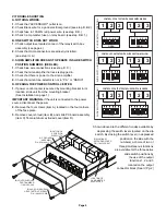
4
P
osition
S
lide
S
witch
Numbered
1,
with
3 L
E
D
’s.
5 SPST P
ush
B
utton
S
witches
,
Numbered
from
2
to
6
.
T
hese switches are
connected to the circuit.
G
reen
Y
ellow
R
ed
PCC
-
S
9
R
F
RONT
VI
E
W
S2
S3
S4
S5
S6
S
7
1 SPST M
omentary
C
ontact
P
ush
B
utton
S
witch. Numbered
7
.
T
his switch is Isolated
from the circuit.
W
ire Harness with
R
ed
P
ositive
(
+
) 12 V
olts
DC
A
nd
B
lack
G
round
(
-
)
W
ires.
B
oth assembled
to an
A
mp
2 P
osition
S
ocket
C
onnector.
20 A
mp
O
utput Fuses.
Numbered from
1
to
8
.
6
Inch long
P
igtail
C
onnector
A
ssembly
with an
A
mp
2
P
osition
S
ocket
C
onnector.
P
igtail
is to be crimped to
customer supplied
cable.
(S
ee
P
g.
2
III.
B
.
)
PCC
-
S9R
C
onnector
K
it
,
P/
N 4
6
-
072550
4-
00
To Ignition
Circuit
10GA R
ed
W
ire to be
C
onnec-
ted to
12 V
olt
DC P
ower
S
ource.
P
ower Input to be fused with
50 A
mp Fuse
C
ustomer
S
upplied.
A
mp
6
4
0905
-
1 P
ush-on
C
onnector.
T
o be inserted into
O
utput 4 located in rear of unit.
13
inch long
, 22GA B
lue
W
ire
A
ssembly
,
is to be used only if
the system is to be connected
to a
S
iren
A
mplifier.
F
1
F
2
F
3
F
4
F
5
F
6
F7 F8
1
2
3
4
5
6
7
8
9
1
0
11
12
PCC
-
S
9
R REAR
VI
E
W
O
utput
C
onnector
B
lock...
R
elay
B
oard
S
chematic...
R
eference
C
hart.......
Pg. 2
Pg. 5
This Page
6
Function
W
indows.
B
acklighted by
R
ed
/G
reen
L
E
D
’s.
P
osition
1R
ed
(
+
)P
ositive
P
osition
2B
lack
(
-
)
Negative
T
o
S
iren
A
mplifier
(O
ptional
)
WARNING:
All customer suppled wires that connect to
the positive (+) terminal of the battery, must be sized to
supply at least 125% of the maximum operating current,
and fused “at the battery” to carry that load.