background image

Westinghouse Outdoor Power Equipment, LLC | 25

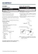
LONG TERM STORAGE

Even properly stabilized fuel can leave residue and cause 

corrosion if left long term. If storing the generator for two to 

six months, drain the float bowl to prevent gum and varnish 

buildup in the carburetor. 

DRAINING THE FLOAT BOWL

1. 

Turn the fuel tank valve to the OFF position.

2. 

Locate the drain screw on the bottom of the carburetor 

float bowl. 

3. 

Place an appropriate gasoline container under the drain 

screw to catch the drained fuel.

4. 

Loosen the float bowl drain screw and allow the fuel to 

drain. Tighten the float bowl drain screw. 

DRAINING THE FUEL TANK

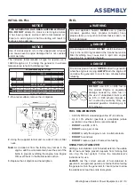
If storing the generator for longer than six months, drain 

the fuel tank to prevent fuel separation, deterioration, and 

deposits in the fuel system. 

1. 

Unscrew the fuel tank cap. Remove the fuel screen filter 

by slightly compressing it while removing it from the 

tank. 

2. 

Using a commercially available gasoline hand pump 

(not included), siphon the gasoline from the fuel tank 

into an approved gasoline container. 

DO NOT

 use an 

electric pump. 

3. 

Reinstall the fuel screen filter and the fuel tank cap. 

4. 

Start the generator and allow it to run until the generator 

engine stops. 

5. 

Push the battery switch to the OFF position. 

6. 

Disconnect the battery quick-connect plugs. 

7. 

Remove the spark plug. 

8. 

Put a teaspoon of engine oil into the cylinder and pull the 

recoil handle until resistance is felt. At this position the 

piston is coming up on its compression stroke and both 

valves are closed. Storing the engine in this position will 

help prevent internal corrosion. Return the recoil handle 

gently.  

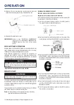
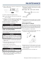
FUEL VALVE MAINTENANCE

The fuel valve is equipped with a fuel sediment cup, screen, 

and o-ring. The fuel valve does not require servicing if the 

unit is properly maintained with fresh, clean fuel. If fuel-

related troubleshooting is required, perform fuel valve 

maintenance. 

1. 

Allow the generator to cool completely. 

2. 

Turn the fuel valve to the OFF position. 

3. 

Remove the sediment cup from the fuel valve. Remove 

the o-ring and screen.

4. 

Wash the sediment cup, o-ring, and screen in a 

nonflammable solvent. Dry thoroughly. 

5. 

Place the screen and o-ring into the fuel valve. Install 

the sediment cup and tighten securely. 

6. 

Turn the fuel valve to the ON position and check for 

leaks. Replace the fuel valve if there is any leakage. 

7. 

Reinstall the spark plug. Leave the spark plug boot 

disconnected to prevent accidental starting. 

MAINTENANCE

Summary of Contents for WGen7500c

Page 1: ...SER MANUAL DO NOT RETURN THIS PRODUCT TO THE STORE If you have questions or need assistance please call customer service at 855 944 3571 WGen7500c Portable Generator 7500 Running Watts 9500 Peak Watts...

Page 2: ...anual can result in serious injury or death SAVE THESE INSTRUCTIONS TABLE OF CONTENTS INTRODUCTION DISCLAIMERS 2 ALL RIGHTS RESERVED 2 SPECIFICATIONS 3 SAFETY SAFETY DEFINITIONS 4 SAFETY SYMBOLS 4 SAF...

Page 3: ...s up to 104 F 40 C If needed this product can be operated at temperatures ranging from 5 F 15 C 122 F 50 C for short periods If the product is exposed to temperatures outside of this range during stor...

Page 4: ...voided could result in death or serious injury CAUTION Indicates a hazardous situation which if not avoided could result in minor or moderate injury NOTICE Indicates a situation which can cause damage...

Page 5: ...ly installed and the electrical output has been verified by a qualified electrician The connection must isolate the generator power from utility power and must comply with all applicable laws and elec...

Page 6: ...allow the generator s gas tank to overflow when filling Shut down the engine and allow it to cool for two minutes before adding gasoline or oil to the generator NEVER remove the fuel cap when the gene...

Page 7: ...ttery powered carbon monoxide alarm s in your home WARNING Automatic shutoff accompanied with a flashing RED light in the CO Sensor portion of the control panel is an indication that the generator was...

Page 8: ...the TEST C button located on the front of the receptacle to trip the device This should immediately stop the flow of electricity and shut off the lamp If the electricity is not stopped DO NOT use this...

Page 9: ...Westinghouse Outdoor Power Equipment LLC 9 SAFETY LABELS AND DECALS SAFETY...

Page 10: ...s Receptacles can supply a maximum of 20 Amps 6 120 Volt AC 20 Amp Duplex GFCI NEMA 5 20R Receptacles Receptacles can supply a maximum of 20 Amps 7 20 Amp AC Circuit Breakers Circuit breakers limits t...

Page 11: ...Westinghouse Outdoor Power Equipment LLC 11 COMPONENTS GENERATOR COMPONENTS...

Page 12: ...Assembly wrench Wheel and mounting foot components Item Quantity Mounting foot 2 Flange bolt M8 4 Wheel 2 Axle pin 2 Washer 2 Cotter pin 2 If any parts are missing contact our service team at service...

Page 13: ...fuel item that is broken cut torn or damaged DANGER Fire and explosion hazard DO NOT overfill fuel tank Fill only to the red fill ring located in the in tank fuel screen filter Overfilling may cause f...

Page 14: ...e red maximum fill ring on the fuel screen filter visible in the filler neck 5 Install the fuel cap NOTICE Fuel can damage paint and plastic Use caution when filling the fuel tank Damage caused by spi...

Page 15: ...tairs next to walls or buildings or in any other location that will not allow for adequate cooling of the generator and or the muffler DO NOT contain generators during operation DANGER Asphyxiation ha...

Page 16: ...anel If your unit was shipped without a key fob contact Westinghouse customer service The generator can be started remotely from up to 99 feet 30 meter using the remote start key fob Note As the batte...

Page 17: ...he choke and begin the start sequence If the engine fails to start the generator will attempt to start the engine two more times STOPPING THE ENGINE 1 Turn off and unplug all connected electrical load...

Page 18: ...Conditioner 11 000 BTU 1010 1600 TV Tube Type 300 0 RV Refrigerator 180 600 Radio 200 0 Light 75 Watts 300 0 Coffee Maker 600 0 2590 Total Running Watts 1600 Highest Starting Watts Total Running Watts...

Page 19: ...resulting in death or serious injury Before connecting an AC appliance or power cord to the generator Use grounded 3 prong extension cords tools and appliances or double insulated tools and appliance...

Page 20: ...unit level during transport to minimize the possibility of fuel leakage or if possible drain the fuel or run the engine until the fuel tank is empty before transport The generator wheels are only int...

Page 21: ...ime Hours The maintenance codes will be displayed until the unit is turned off Refer to the Maintenance section for specific procedures Maintenance Code Required Maintenance P25 Change engine oil P50...

Page 22: ...eather change the oil more frequently Ambient air temperature will affect engine oil performance Change the type of engine oil used based on weather conditions Check the engine oil level before each u...

Page 23: ...the spark boot directly away from the engine 3 Clean the area around the spark plug 4 Remove the spark plug with the included spark plug socket wrench NOTICE NEVER apply any side load or move the spa...

Page 24: ...nnect the quick connect plug NOTICE Dispose of the used battery properly according to the guidelines established by your local or state government STORAGE Proper storage preparation is required for tr...

Page 25: ...Start the generator and allow it to run until the generator engine stops 5 Push the battery switch to the OFF position 6 Disconnect the battery quick connect plugs 7 Remove the spark plug 8 Put a teas...

Page 26: ...rocker arms should be loose at TDC on the compression stroke If they are not rotate the engine 360 5 Insert a feeler gauge between the rocker arm and the valve stem to measure valve clearance Intake...

Page 27: ...service toll free at 1 855 944 3571 Engine starts then shuts down Out of fuel Refuel Incorrect engine oil level Check engine oil level Dirty air filter Clean the air filter Contaminated fuel Drain th...

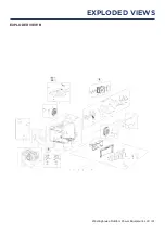
Page 28: ...28 Westinghouse Outdoor Power Equipment LLC EXPLODED VIEWS AND PARTS LISTS EXPLODED VIEW A EXPLODED VIEWS...

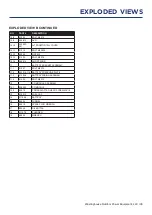
Page 29: ...MBLY 9 1 271005 CYLINDER HEAD 9 2 271702 INTAKE VALVE 9 3 275902 EXHAUST VALVE NO PART DESCRIPTION 9 4 261807 INTAKE VALVE SPRING LOWER SEAT 9 5 93513 VALVE SEAL 9 6 266002 VALVE SPRING 9 7 260802 VAL...

Page 30: ...WHEEL NUT 15 RECOIL STARTER ASSEMBLY 15 1 91325 BOLT M6X12 15 2 264738 221B STARTER ASSEMBLY 15 2 1 5910 221 RECOIL STARTER 15 2 2 5943 HANDLE 16 STARTER MOTOR ASSEMBLY 16 1 97415 STARTING MOTOR 16 2...

Page 31: ...Westinghouse Outdoor Power Equipment LLC 31 EXPLODED VIEW B EXPLODED VIEWS...

Page 32: ...120030 ENGINE ASSEMBLY 4 3 549603 DUST BOARD 4 4 91322 BOLT M5X12 4 5 90016 NUT M6 4 6 539602 CRANKCASE COVER 5 CARBON CANNISTER ASSEMBLY NO PART DESCRIPTION 5 1 95123 CARBON CANISTER AND FUEL TANK C...

Page 33: ...23 BOLT M5X16 10 14 544610 SHORT WIRE 11 BATTERY BRACKET ASSEMBLY 11 1 91327 BOLT M6X12 11 2 542614 116 BATTERY PRESSURE PLATE 11 3 512058 BATTERY WIRING ASSEMBLY 11 4 91325 BOLT M6X12 12 CO MODULE AS...

Page 34: ...34 Westinghouse Outdoor Power Equipment LLC SCHEMATICS SCHEMATICS SCHEMATICS...

Reviews: