background image

Lit. No. 64369, Rev. 04 

21 

June 15, 2010

OPERATIONAL TESTS AND FINAL ADJUSTMENTS

FINAL INSPECTION AND ADJUSTMENT

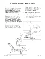
1.  Attach the snowplow to the vehicle mount. With 

snowplow lowered to the ground and on level 
pavement, measure the dimension from the 
ground to the center of the pivot bar cap screw. 
This dimension must be 9-3/4" to 11-1/4".

2.  With the snowplow attached and on the ground, 

place the stand arm in the lower position with 
the lock pin engaged and with the stand shoe 
fully retracted in the "up" position. Measure the 
distance from the ground to the bottom of the 
stand shoe. This distance should be 1-3/8" to 
2-1/8". The stand can be adjusted to achieve this 
dimension by removing the roll pin and selecting 
the proper hole in the stand stem. When the stand 
height is correct, cut and remove the spring tie.

3.  Final lift chain link adjustment must be made 

after the snowplow is assembled with the proper 
pivot plate position. On a level surface with the 
snowplow on the ground and the lift ram fully 
collapsed, attach the chains to the lift arm hooks 

in the tightest possible link. This adjustment will 
provide for optimum transport height, blade 

fl

 oat, 

and stacking stop clearance. When chain tension 
is correct, the A-frame will not contact the lift 
frame when the blade is fully raised.

4.  Fully raise the blade and verify that it does not 

block the headlamp beams. If the blade blocks the 
headlamp beams, lower the blade to the ground, 
collapse the lift ram and lengthen each chain by 
one link. Repeat this process, lengthening the 
chains by one link each time, until the blade does 
not block the headlamp beams.

Roll Pin

(Against

Stand Body)

9-3/4" to 11-1/4"

1-3/8" to 2-1/8"

Summary of Contents for MIDWEIGHT

Page 1: ...ons CAUTION Read this document before installing the snowplow CAUTION See your WESTERN outlet Web site for specific vehicle application recommendations before installation The Selection List has specific vehicle and snowplow requirements Western Products PO Box 245038 Milwaukee WI 53224 9538 www westernplows com ...

Page 2: ......

Page 3: ... CAUTION INSTRUCTION LABELS Become familiar with and inform users about the warning caution labels on the back of the blade and the instruction label on the headgear NOTE If labels are missing or cannot be read see your sales outlet Instruction Label Warning Caution Label LOWER BLADE WHEN VEHICLE IS PARKED DO NOT EXCEED GVWR OR GAWR INCLUDING BLADE AND BALLAST REMOVE BLADE ASSEMBLY BEFORE PLACING ...

Page 4: ...NING Hydraulic fluid under pressure can cause skin injection injury If you are injured by hydraulic fluid get medical attention immediately SAFETY PRECAUTIONS Improper installation and operation could cause personal injury and or equipment and property damage Read and understand labels and the Owner s Manual before installing operating or making adjustments WARNING Lower blade when vehicle is park...

Page 5: ...cal components CAUTION Read instructions before assembling Fasteners should be finger tight until instructed to tighten according to torque chart Use standard methods and practices when attaching snowplow including proper personal protective safety equipment FIRE AND EXPLOSION Be careful when using gasoline Do not use gasoline to clean parts Store only in approved containers away from sources of h...

Page 6: ... Shown Quadrant Cylinder Bracket Blade Brackets Spring Bracket 5 8 Nuts 5 8 x 4 Eyebolt 3 4 x 5 3 8 Clevis Pin 3 4 Washer 5 32 x 1 1 2 Cotter Pin Trip Spring A Frame Chain Assembly Stand Shoe Stand Pivot Bar Pivot Plates Lower Lift Frame Upper Lift Frame Lift Arm Blade Guide Assembly Trip Stop Cushion Pivot Pin Eyebolt Bracket ...

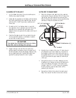
Page 7: ...ock in place CAUTION Overtightening springs will not increase blade trip force and can damage the springs A FRAME TO QUADRANT 1 Place the A frame nose plate over the quadrant pivot section Secure with one 7 8 x 9 cap screw pivot bolt three flat washers and a locknut as shown Tighten locknut as much as possible while allowing A frame and quadrant to pivot 2 Position the rod ends of the two 10 rams ...

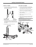
Page 8: ...hten locknut securely against jam nut NOTE When properly adjusted the pivot bar should pivot freely without any looseness CHAIN TO A FRAME 1 Use a hook or piece of wire to pull the end of the chain through the plastic tube The end link of the chain must be fully exposed 2 Insert ends of the 3 8 x 1 1 2 U bolt through the chain and then down through the holes in the chain bracket on the A frame and...

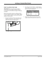
Page 9: ...must be installed if required and the vehicle must be parked on a level surface 1 Measure the distance d from the ground to the top edge of the receiver bracket Measure both sides and determine average value d Top Edge of Receiver d 2 Use dimension d from Step 1 and the following chart to determine the proper pivot plate mounting position and pivot hole selection Pivot Plate Configuration Chart Di...

Page 10: ...he two lower holes in the pivot plates for configurations 1 and 2 Configuration 3 uses only the lower hole This provides three different height adjustment positions For all configurations pivot pins must be positioned with the notches in the pivot pins facing up and the slots in the pivot pins aligned with the bottom holes at the rear of the pivot plates Note that the pivot pins are never installe...

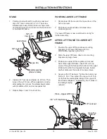
Page 11: ...ole in the front of the pivot plate Retain with a locknut Repeat on other side 5 Tighten all fasteners according to torque chart STAND SHOE Initial stand shoe height adjustment is based on height configuration chart A final adjustment of stand shoe will be made after attaching snowplow to vehicle 1 Slide the stand shoe into the stand tube and align 1 4 hole in stand tube with 1 4 hole in stand sho...

Page 12: ...ll another plate over the ends of the cap screws 4 Secure with 3 8 locknuts Tighten the bottom nut first to 31 ft lb Then tighten the top nut to 31 ft lb Verify that the rectangular tubing of the upper lift frame has collapsed indicated by the 3 sides of the tubing bulging outward STAND 1 Position stand with latch hook facing rear and align 3 4 hole in stand to 3 4 x 6 cap screw installed previous...

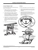
Page 13: ...ft lb Valve block should be tight rearward against bracket 4 Tighten the two 1 4 locknuts from Step 2 Lift Arm The lift arm and hardware are found in the A Q L box 1 With chain hooks forward and up position lift arm ends around upper lift frame vertical supports and align holes 2 On each side install a 3 4 plastic washer between the outside leg of the lift arm and the lift frame vertical support I...

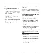
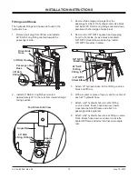
Page 14: ...mately 20 ft lb Use the following procedure to install hydraulic hoses NOTE Overtightening JIC hose fittings will result in a fractured fitting 1 Screw flare nut onto fitting flare and hand tighten 2 Align hose so there are no twists or sharp bends 3 Using two wrenches hold the hose in position and tighten flare nut 1 8 to 1 4 turn beyond hand tight Final torque on the flare nut should be approxim...

Page 15: ...pipe plug from the front side of valve block and install 3 8 NPTF street elbow oriented up Install 3 8 NPTF breather in elbow 5 Attach 16 hydraulic hose to front fitting on valve block and lift ram 6 With a marker or piece of tape mark the center of each 42 hydraulic hose 7 Attach a 42 hydraulic hose to center fitting on valve block Route hose down over lower cross tube behind lift frame and attac...

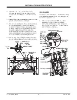
Page 16: ...in Step 6 11 Orient clamp and base as shown and install hoses in their respective side of clamp with sleeves centered in clamp and sleeve openings to inside of clamp Tighten clamp Final position of clamp should be approximately 20 clockwise from horizontal Proper positioning of the hoses in the clamp is necessary to allow complete movement of the snowplow without stressing the hoses 12 If necessar...

Page 17: ... terminals and blades before assembly SNOWPLOW CONTROL HARNESS NOTE Dielectric grease has been applied to coil terminals DO NOT wipe off terminals 1 With the harness strain relief located at lower rear corner of the valve block attach a black orange wire to each valve coil 2 Attach white yellow wire to front coil green wire to center coil and blue wire to rear coil See diagram below 3 Route wires ...

Page 18: ...ch black red battery cable to the POSITIVE motor stud on the hydraulic unit 2 Attach black battery cable and the two black orange wires from the headlamp and control harnesses to motor NEGATIVE ground stud 3 Tighten both stud nuts to 50 60 in lb Do not allow stud to rotate while tightening 4 Install cable boot over bracket on driver s side of the lift frame 5 Insert battery cable connector in cabl...

Page 19: ...function and manually collapse the lift ram all the way after each lowering of the blade Turn the control OFF 6 Fill the reservoir to the top of the fill hole and replace the fill plug WARNING Keep 8 clear of the blade when it is being raised lowered or angled Do not stand between the vehicle and blade or directly in front of the blade If the blade hits or drops on you you could be seriously injur...

Page 20: ...e making adjustment Turn the control OFF 2 Turn the quill IN clockwise to decrease drop speed Turn the quill OUT counterclockwise to increase drop speed 3 Stand clear of the blade when checking adjustment WARNING Keep 8 clear of the blade when it is being raised lowered or angled Do not stand between the vehicle and blade or directly in front of the blade If the blade hits or drops on you you coul...

Page 21: ...stand stem When the stand height is correct cut and remove the spring tie 3 Final lift chain link adjustment must be made after the snowplow is assembled with the proper pivot plate position On a level surface with the snowplow on the ground and the lift ram fully collapsed attach the chains to the lift arm hooks in the tightest possible link This adjustment will provide for optimum transport heig...

Page 22: ...nfused source VEHICLE LIGHTING CHECK 1 Verify the operation of all vehicle front lighting prior to connecting the snowplow harness 2 Check the operation of the snowplow lights with snowplow mounted to vehicle and all harnesses connected Turn signals and parking lamps Parking lamps ON Both vehicle and snowplow parking lamps should be ON at the same time Driver side turn signal ON Both vehicle and s...

Page 23: ...mpleted snowplow will be delivered immediately the Owner s Manual should be reviewed with and given to the purchaser according to the snowplow checklist If the snowplow is completed prior to delivery to the purchaser attach the Owner s Manual Packet to the electrical cable of the cab control for safekeeping ...

Page 24: ... may require or recommend optional equipment for snow removal Do not exceed vehicle ratings with a snowplow Western Products offers a limited warranty for all snowplows and accessories See separately printed page for this important information The following are registered or unregistered trademarks of Douglas Dynamics L L C FloStat MIDWEIGHT UltraMount WESTERN Printed in U S A Western Products PO ...

Reviews: