Lit. No. 64369, Rev. 04
13
June 15, 2010
INSTALLATION INSTRUCTIONS
FloStat
®
HYDRAULIC UNIT
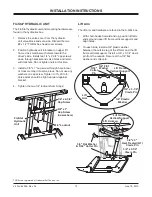
The FloStat hydraulic unit and mounting hardware are
found in the hydraulics box.
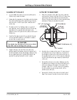
1. Remove the valve cover from the hydraulic
unit valve block and set aside. Discard the two
#8 x 1/2" TORX
®
hex head cover screws.
2. Position hydraulic unit in bracket on upper lift
frame cross member with valves toward the
driver's side. Install two 1/4" x 2-3/4" cap screws
down through bracket and valve block and retain
with locknuts. Do not tighten nuts at this time.
3. Install a 3/8" x 1" cap screw through hole in rear
of cross member into valve block. Do not use any
washers on cap screw. Tighten to 15–20 ft-lb.
Valve block should be tight rearward against
bracket.
4. Tighten the two 1/4" locknuts from Step 2.
Lift Arm
The lift arm and hardware are found in the A,Q&L box.
1. With chain hooks forward and up, position lift arm
ends around upper lift frame vertical supports and
align holes.
2. On each side, install a 3/4" plastic washer
between the outside leg of the lift arm and the lift
frame vertical support. Install a 3/4" x 3-1/4" clevis
pin from the outside. Secure with a 3/4"
fl
at
washer and cotter pin.
TORX
®
is a registered (
®
) trademark of Textron, Inc.
1/4" x 2-3/4"
Cap Screw
3/8" x 1"
Cap Screw
(no washers)
1/4" Locknut
FloStat
Hydraulic
Unit
3/4" Flat Washer
& 5/32" Cotter Pin
3/4" x 3-1/4"
Clevis Pin
3/4" x 3"
Heat Treated (HT)
Clevis Pin
Lift Arm Leg
Lift Frame
Vertical Support
Lift Frame
Vertical Support
3/4" Plastic
Washer
3/4" x 3-1/4"
Clevis Pin
Lift
Arm
5/32"
Cotter
Pin
3/4" Flat
Washer
Summary of Contents for MIDWEIGHT
Page 2: ......


