Lit. No. 64369, Rev. 04
12
June 15, 2010
INSTALLATION INSTRUCTIONS
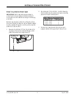
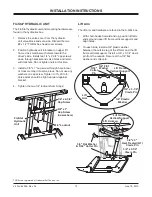
POSITION LOWER LIFT FRAME
1. Rotate lower lift frame until the top surface of the
horns are level.
2. Push down on stand tube until stand shoe
contacts ground.
The lower lift frame is now positioned correctly for
further assembly.
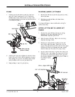
UPPER LIFT FRAME TO LOWER LIFT
FRAME
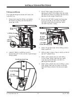
1. Position the upper lift frame above mounting
brackets on the lower lift frame with the
WESTERN
®
logo facing the front.
2. Slide the upper lift frame down onto mounting
brackets and align holes.
3. Position one upper lift frame plate on front and
back of the upper lift frame. Insert 3/8" x 4" cap
screws through the holes at the bottom of the upper
lift frame from the front towards the back. Install
another plate over the ends of the cap screws.
4. Secure with 3/8" locknuts. Tighten the bottom nut
fi
rst to 31 ft-lb. Then tighten the top nut to 31 ft-lb.
Verify that the rectangular tubing of the upper lift
frame has collapsed—indicated by the 3" sides of
the tubing bulging
outward.
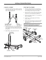
STAND
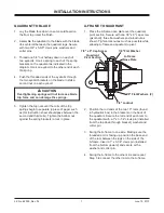
1. Position stand with latch hook facing rear and
align 3/4" hole in stand to 3/4" x 6" cap screw
installed previously. Slide stand over cap screw
and engage lock pin on stand into the bottom slot
in the lower lift frame
2. Install a 3/4" locknut and tighten to 25 ft-lb. Then
loosen the nut 1/4 turn. When adjusted correctly,
after pulling lock pin out, the stand should rotate
with moderate effort and no looseness felt.
3. Repeat Steps 1 and 2 on other side.
Horn Top
Surface
Support
9.0"
Stand
Tube
Stand
Shoe
3/8" x 4" Cap Screw
Plate – Upper Lift Frame
3/8" Locknut
3/4" x 6"
Cap Screw
3/4" Locknut
Latch Hook
Lock Pin
Stand Assembly
(Driver's Side)
Summary of Contents for MIDWEIGHT
Page 2: ......


