List of figures
Page
55
of
55
21
List of figures
Fig. 1 - Danger zone ..................................................................................................... 10
Fig. 2 - Dimensions ...................................................................................................... 18
Fig. 3 - Engine dimensions ........................................................................................... 19
Fig. 4 - Inclination ......................................................................................................... 20
Fig. 5 - Controls ............................................................................................................ 23
Fig. 6 - Oil level ............................................................................................................ 24
Fig. 7 - Hydraulic oil level ............................................................................................. 24
Fig. 8 - Fuel supply ....................................................................................................... 24
Fig. 9 - STG-125 ........................................................................................................... 25
Fig. 10 - Seat adjustment ............................................................................................. 27
Fig. 11 - Handbrake ...................................................................................................... 27
Fig. 12 - Gearbox release ............................................................................................. 27
Fig. 13 - Accelerator pedal ........................................................................................... 28
Fig. 14 - Steering .......................................................................................................... 28
Fig. 15 - Speed control ................................................................................................. 28
Fig. 16 - Controls .......................................................................................................... 28
Fig. 17 - Attachments ................................................................................................... 29
Fig. 18 - Fitting attachments ......................................................................................... 30
Fig. 19 - Tensioning V-belt ........................................................................................... 34
Fig. 20 - Replacing V-belt ............................................................................................. 35
Fig. 21 - Tensioning the lock chain ............................................................................... 35
Fig. 22 - Cleaning the air filter ...................................................................................... 35
Fig. 23 - T-handle switch .............................................................................................. 39
Fig. 24 - Vehicle ........................................................................................................... 39
Fig. 25 - Cover .............................................................................................................. 45
Fig. 26 - Base frame ..................................................................................................... 46
Fig. 27 - Power lifter ..................................................................................................... 47
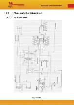
Fig. 28 - Hydraulic lines ................................................................................................ 48
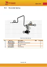
Fig. 29 - Rear wheel bearing ........................................................................................ 49
Fig. 30 - Foot pedal ...................................................................................................... 50
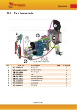
Fig. 31 - Main components ........................................................................................... 51
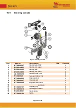
Fig. 32 - Steering console ............................................................................................ 52

