background image

Section VES-R00-20A

030-101639 Rev. B

R

7

0802IARB

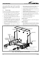
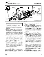
Figure 7.

Open, Isometric, Right-Side View of VESR-14 Model (Cover Removed)

Wood studs, 16”

on centers 

(for

drywall  applications)

Plywood, drywall, or

concrete wall

Center

mounting

hole 

(used to

self-level the

unit)

Corner mounting hole*

(4 total)

Cover

(VERS-14 model only)

* Mounting screw heads must fit through

the large round part of the keyholes

Cable Race-way

(slotted duct)

(1 RU high,

VESR-14 only)

Snap-on

cover

Enlarged view of Bend Radius Protection

Boot 

(guide fiber cables through the slots)

Inset A

Inset B

(VERS-14 only)

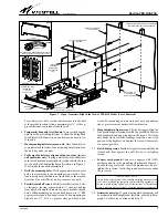
External D-rings mount at center

holes (see Figure 8 & Figure 8)

Wall of

SwingRacks, 3 high.

Inset C

heavy-duty screw, bolt, or other wall-fastener into the wall
at the marked location. Allow approximately 1/4" of the ap-
proved fastener to protrude from the wall.

4.

Temporarily hang and level the unit. 

Temporarily hang the

unit from the protruding fastener to allow the SwingRack
to self-level itself. If desired, a hand level can be used to lev-
el the unit.

5.

Mark mounting-hole locations on wall. 

 Once the unit is lev-

el, quickly mark the other, four, mounting hole locations on
the wall. Set aside the unit.

6.

Verify marked holes are aligned with wood studs

 (for dry-

wall applications only).

 If using a wall with a drywall surface,

ensure each marked mounting hole is aligned with the cen-
ter of a wood stud behind the drywall, as shown in Figure 7.
If not, make the needed adjustments.

7.

Drill the mounting holes. 

Drill appropriately-sized pilot

holes, to accommodate the mounting screws, bolts, or fas-
teners being used (hardware not included), at the marked
locations. 

Do not drill holes too big, to ensure a snug fit

.

8.

Partially install all screws. 

Partially install all screws, bolts,

or fasteners, leaving approximately ¼" inch protruding
from which to hang the unit via the unit’s keyhole-shaped
holes. When mounting on a wood backboard, use ¾" #10
or greater steel pan-head wood screws. When mounting on
drywall, use 1¼" #10 or greater steel pan-head wood

screws. For mounting on a concrete wall, use an equivalent
size or greater cement anchor/bolt combination.

9.

Hang SwingRack from screws. 

Lift the unit again, align the

four protruding wall fasteners with the predrilled holes in
the SwingRack, and hang the unit on the screws. Verify the
unit hangs freely (without binding) from the narrow top
portion of the keyholes, and adjust the screws if necessary
to ensure a good fit.

10.

Finish driving screws. 

Finish driving all screws until the unit

is flush and firm against the wall. Do not over-tighten
screws.

11.

Connect earth ground. 

Connect an approved #6 AWG

earth ground wire to the ground lug (lug shown in Figure 4).
Loosen the lug’s set screw, insert the ground wire, and re-
tighten the set screw. Verify the ground wire is secure under
the set screw.

- GROUNDING NOTE -

Always follow safety precautions, standard operating procedures and
local codes for grounding equipment when installing, upgrading, re-
pairing or maintaining equipment. All instructions or information
herein is subordinate to local codes, operating procedures or practices.

12.

Determine next step

. If customer-supplied equipment will

be mounted in the SwingRack at this time, proceed to Para-
graph 3.5; otherwise, continue with Step 13.

Summary of Contents for VirtualEdge VESR-00

Page 1: ... Unit RU high equipment in the SwingRack saves valuable rack space for other equipment makes use of previously vacant wall space and facilitates installation maintenance and testing proce dures by rotating the attached equipment down to a comfortable easy access horizontal height The key feature of the SwingRack is the matching set of 90_ rotating arms rails which imitate and duplicate the width b...

Page 2: ...nagement and protection S Spring loaded slam bolt latches one in each arm securely lock the SwingRack s arms in the up position S Holes and slots strategically placed for cable tie downs S Sturdy but light weight material steel back plate and alumi num swing arms and support plate S Ground lug accepts 6 AWG ground wire S Flexible heavy duty ground strap VESR 00 model only S Two external 3 D rings ...

Page 3: ...mmon to all models in the series 2 1 1 Construction Design and Material The one piece SwingRack takes advantage of the available and vacant wall space in crowded equipment rooms so 1 or 2 RU high equipment that typically is mounted in 19 or 23 equipment racks can be mounted on a wall leaving valuable rack space for taller equipment or additional equipment Each SwingRack model consists of a durable...

Page 4: ... posi tion if desired The rings are made of a flexible aluminum and are designed with an angled cut or slit on the outer edge to facil itate cable routing ingress and egress into and out from the internal confines of the D ring Simply press on the top or bot tom half of the D ring and route the cables through the provided gap in the D ring 2 1 4 2 Slam bolt Latch When the swing arms are in the up ...

Page 5: ...ing it off place the rear wall of the race way against the adapter ears align the holes then attach the race way to the ears with the provided hardware Route cables through the race way to the slotted hole or tab closest to the equipment s desired connec tor and press on the race way slot s flexible tab to create space to enable the cable to enter the slotted hole When all cables are connected or ...

Page 6: ...tween any multiple installations or other equipment The distance from the cable entry point should be consistent with local installation practices Figure 6 Corner Mounting Hole Locations and Dimen sions VESR XX Front View Open Position Adapter ears installed at end of open arms Self leveling center keyhole for drywall walls center between 16 studs See Table 2 for more dimensions CAUTION When using...

Page 7: ...date the mounting screws bolts or fas teners being used hardware not included at the marked locations Do not drill holes too big to ensure a snug fit 8 Partially install all screws Partially install all screws bolts or fasteners leaving approximately inch protruding from which to hang the unit via the unit s keyhole shaped holes When mounting on a wood backboard use 10 or greater steel pan head wo...

Page 8: ...U is available attach the D rings to the center set of holes in the installed adapter ears first mount the adapter ears to the swing arms then mount the D rings to the ears using the provided hardware 5 Install race way slotted duct if applicable For the VESR 14 model only if desired and if one RU is avail able the provided cable race way can be installed at this time in the top RU position for ca...

Page 9: ...the lock and turn the key clockwise to rotate the lock s tab into the slot pro vided for it in back plate s top flange 3 5 2 Mounting 19 Equipment If the equipment to be mounted on the SwingRack was de signed for 19 rack mounting first install the provided adapter ears onto the ends of each swing down arm before attaching the equipment to the arms Follow the steps below 1 Place arms in down positi...

Page 10: ...y calling or using one of the options shown below Once an RMA number is obtained return the defective unit freight prepaid along with a brief problem description to the address we will provide to you when you contact us Voice 630 375 4211 email rgmdept westell com Replacements will be shipped in the fastest manner consistent with the urgency of the situation Westell will continue to repair or repl...

Reviews: