


Section VES-R00-20A
030-101639 Rev. B
R
2
0802IARB
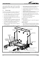
tomer premises hand-off point. See Part 3 for further
wall-mounting instructions. Either single or multiple Swing-
Racks can be wall-mounted in an equipment room (see Inset C
in Figure 7).
1.5
Product Features
All models in the SwingRack series offer the following fea-
tures. For detailed information on all features, see Part 2.
S
Easy wall-mounting on concrete or Telco-approved ply-
wood walls, or drywall with wood studs on 16" centers
S
Four, keyhole-shaped, mounting holes (16" centers)
S
Fifth, center, keyhole-shaped mounting hole facilitates unit
leveling during installation
S
Two, built-in, swing-down, mounting arms (rails) enable
mounting of equipment designed for 23" equipment racks
S
Two swing-down arm positions: up (vertical) for storage, or
rotated 90
_
down (horizontal) for installer work
S
Adapter ears enable mounting of equipment designed for
19" equipment racks
S
Accepts equipment up to 2 RUs high (or two 1-RU units)
S
Horizontal support/name plate provides additional equip-
ment support when arms are in the down position
S
Accepts an optional fiber splice tray (mounts in arm)
S
Internal D-rings in each swing-down arm provide cable
management and protection
S
Spring-loaded slam-bolt latches (one in each arm) securely
lock the SwingRack’s arms in the up position
S
Holes and slots strategically-placed for cable tie-downs
S
Sturdy but light-weight material: steel back plate and alumi-
num swing-arms and support plate
S
Ground lug, accepts #6 AWG ground wire
S
Flexible, heavy-duty ground strap
VESR-00 model only:
S
Two, external, 3" D-rings for courtesy cable management
outside of the arms
VESR-14 model only:
S
Fiber management spool in arm facilitates fiber cable man-
agement and storage, and locking protective cover, with key
S
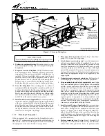
Bend-radius protection boot (see Inset B of Figure 7)
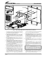
Figure 3.
Open, Isometric, Right-Side View of VESR-14 Model
Fiber cable management spool*
Interior cable management D-ring
Slam-bolt latch
Orange, flexible, fiber-
cable protection tube
Recessed, keyhole-
shaped, mounting
hole
Swing-down arm,
down/horizontal position
(for mounting 23-inch
rack-type equipment
up to 2 RU high)
Support/
name plate
Adapter ears
(for use with 19” rack-
type equipment)
Cable access hole
Tie-down slots
(for cables in-
side the arm)
Slot for cover lock*
Center keyhole used to level
unit during installation
Latch catch-hole
(locks slam-bolt latch)
Mounting location for optional splice tray
(D-ring attaches to middle
set of holes in adapter ears)
External D-ring
(VESR-00 model)
*VESR-14 only
Tie-down
holes
(for cables out-
side the arm)


