


Section VES-R00-20A
030-101639 Rev. B
R
3
0802IARB
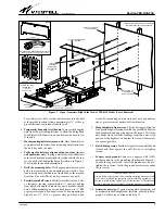
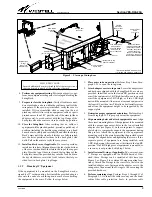
Figure 4.
Closed View of VESR-14 Model (without cover)
Locking cover
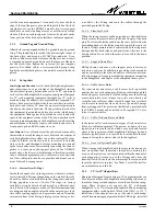
Figure 5.
Closed View of VESR-14 Model (Includes Cover)
Ground strap
Ground lug
Support/Name plate
Adapter ears
(for installation of 19” equipment)
Latch-release
knob
Cable access
hole
S
Protective cable race-way (slotted flexible duct, mounts
from one arm-end to the other)
S
Flexible, orange, fiber-cable protection tube protects
cables as they enter the wall-mount rack
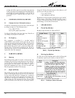
Feature / Option
VESR-00
VESR-14
Back plate, with 5 keyholes
n
n
Two 90
_
swing-arms
n
n
Name / Support plate
n
n
Adapter ears, for 19”
4
4
Internal-arm D-rings
6
5
External-arm 3” D-rings
2
Locking Front Cover
n
Flexible Fiber Protection Tube*
n
Fiber Management Spool*
n
Cable Race-way (duct)*
n
Bend Radius Protection Boot*
2
Ground Strap
n
n
Ground Lug
n
n
Accepts optional splice tray
n
n
n
= equipped. * Asterisked features facilitate fiber cable management and protection.
Table 1. Options and Features of SwingRack Models
2.
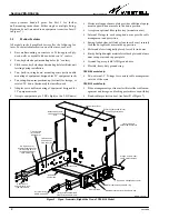
FEATURES AND OPTIONS
Westell offers two versions of the SwingRack, as shown in
Table 1. Each model contains a different feature subset and op-
tion package. This section groups and describes the features that
are common to all models, the fiber management and protection
features, and other options which make each model unique.
2.1
Common Features
The features described in Paragraphs 2.1.1 to 2.1.5 below are
common to all models in the series.
2.1.1
Construction, Design, and Material
The one-piece SwingRack takes advantage of the available and
vacant wall space in crowded equipment rooms, so 1 or 2 RU-
high equipment that typically is mounted in 19" or 23"
equipment racks can be mounted on a wall, leaving valuable
rack space for taller equipment or additional equipment. Each
SwingRack model consists of a durable, steel, specially-de-
signed and molded back plate and two, aluminum, opposing
and symmetrical, swing-down rails or arms attached to the back
plate, each of which are further described below. The painted
surface is attractive and protective.
2.1.2
Back Plate
The steel back plate is the biggest component of the Swin-
gRack. It contains five recessed, predrilled, keyhole-shaped
mounting holes placed in a rectangular pattern; a top row of
three and a bottom row of two. The outer or corner holes in the
rectangular pattern are 16" apart horizontally, to accommo-
date walls containing wood studs which are 16" apart, on
centers. The keyhole shape of each hole allows easy mounting
by hanging the SwingRack on pre-installed mounting screws or
fasteners whose heads can fit through the large-diameter area
of the keyholes. For faster installation, the SwingRack can be
self-leveled" by temporarily and initially hanging the unit
from the center hole on a single centered wall-fastener, then
marking the remaining four mounting hole locations. The re-
cessed keyholes keep the heads of the wall fasteners from
contacting any equipment mounted in the SwingRack. The
wide, 90
_
, top and side flanges on the back plate serve to pro-


