Section VES-R00-20A
030-101639 Rev. B
R
4
0802IARB
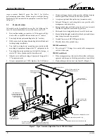
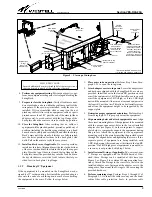
tect the mounted equipment. A centered slot near the front
edge of the top flange accepts a matching lock tab on the lock-
ing front cover, for the VESR-14 model only. A rectangular
small hole on each side flange serves as a latch-catch for the
slam-bolt latch on each swing-arm. A few tie-down slots on the
lower portion of the back plate facilitate cable management.
2.1.3
Ground Lug and Ground Strap
All models come equipped with both a ground lug and a ground
strap. The ground lug is located at the bottom right corner of
the back plate, and accepts a #6 AWG ground wire. Use a
slotted or blade screwdriver to loosen the lug’s set screw, insert
a company-approved ground wire into the space provided un-
der the screw, then tighten the set screw, all per company
practice. For added safety, a factory-installed ground strap
bonds the metallic back plate to the metallic arms of the Swin-
gRack.
2.1.4
Swing-Arms
Arm Design and Function.
A set of sturdy but light-weight alumi-
num swing-arms, one on each side of the SwingRack, imitate
the horizontal spacing between the rails of a 23" equipment
rack, to allow the SwingRack to accept any equipment designed
for 23" rack mounting (equipment designed for 19" racks is
mounted using the adapter ears, explained in Paragraph 2.1.5
below). Each arm is attached to the lower outside corner of the
back plate, and rotates 90
_
from the up or vertical position to
the down or horizontal position. The up position is used after
the equipment is mounted and placed in service, which keeps
the equipment flush against the wall and out of valuable aisle
space in the equipment room or lab. The down position facili-
tates equipment mounting on the SwingRack as well as testing
and maintenance that may require visual and hand access to
front panel options, LEDs, connectors, etc.
Arm Features.
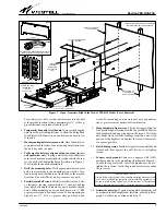
A set of four holes at the end of each arm enables
the installer to attach the adapter ears. Provided in each arm of
each SwingRack unit are either two or three internal D-rings,
a slam-bolt latch, a cable access hole, several cable tie-down
slots or holes, and threaded holes for mounting an optional
splice tray in either arm. Horizontally connecting the arms to-
gether is a cross piece, the support plate. In the VESR-14
model only, a feature set, which includes a flexible protection
tube, a cable management spool, a cable race-way or duct, and
two fiber cable protection boots, provides additional, conve-
nient, fiber cable management.
2.1.4.1
Internal-Arm D-Rings
Inside the channel of each swing-arm are either two or three
factory-installed D-rings (depending on the model ordered).
Four sets of holes are distributed in the swing-arms, and each
D-ring populates one set of holes. The rings are factory
installed, yet can be detached and moved to a different posi-
tion, if desired. The rings are made of a flexible aluminum, and
are designed with an angled cut or slit on the outer edge to facil-
itate cable routing, ingress, and egress into and out from the
internal confines of the D-ring. Simply press on the top or bot-
tom half of the D-ring and route the cables through the
provided gap in the D-ring.
2.1.4.2
Slam-bolt Latch
When the swing-arms are in the up position, a slam-bolt latch
firmly secures the arms to holes in the side flanges of the back
plate. To release the latches and lower the arms, pull or slide the
protruding knobs of the latches inward, toward the center of
the unit. Always maintain hand contact with both swing-arms
during and after latch release, and gently lower the arms to the
down position. Do not allow the arms to free-fall to the down
position.
2.1.4.3
Support/Name Plate
Halfway down each arm, a wide support plate is factory-at-
tached to each arm. In addition to providing joint-arm unity
and cross-stability to the arms, it doubles or serves as a horizon-
tal bottom support for equipment during equipment mounting
in the SwingRack, and triples as the equipment name plate.
2.1.4.4
Cable Access Holes
For convenience and safety, a cable access hole is provided
near the back of each swing-arm. Routing cables through this
hole helps prevent accidental cable damage near the rotating
arm-to-back-plate joint. Always lower the arms slowly and
verify that any cables are either routed through the access hole
or otherwise secured but free and clear of potential damage
from moving parts. The protective flexible tube, provided with
the VESR-14 model and described in Paragraph 2.2.1, also
serves to protect cables.
2.1.4.5
Cable Tie-down Slots and Holes
In the inside wall of each arm are two types of tie-down slots or
holes, for cable management. The narrow tie-down slots are
typically used to secure cables which are routed and located
closer to the center area of the SwingRack. The larger tie-down
holes are typically used to secure cables located
within
the arm
channels, facing the exterior sides of the SwingRack.
2.1.4.6
Area for Optional Splice Tray
When viewing the SwingRack with the arms in the down posi-
tion, an optional and separately ordered kit containing two
screws and a splice tray can be mounted within the channel of
each swing-arm, between two of the D-rings and above the
slam-bolt latch. Two holes in the arms accept the screws, which
secure the splice tray in place. See Table 3 or call Westell for
more information on this kit.
2.1.5
23"-to-19" Adapter Ears
Equipment designed for mounting in 19" equipment racks can
be easily mounted in the SwingRack by installing either two or
four of the four provided adapter ears on the ends of the swing-
arms. These adapter ears convert the 23" wall-mount
SwingRack to a 19" wall-mount SwingRack. When mounting
equipment with a rack height of 1 Rack Unit (1 RU, or 1.75"),
install two of the adapter ears, one at the end of each swing-
arm. When mounting equipment which is 2 RUs high, install all


