030-101704 Rev. C
R
Section VE2-848-CK6-20A
6
1006IARC
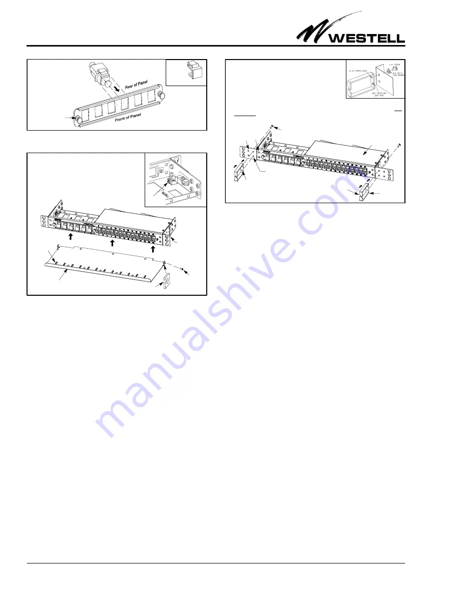
Figure 8. Installing Keystone-type Couplers into LGX Panel
Insert coupler of choice from
the rear of the LGX-type panel.
Depress tab and
insert into hole until
it snaps/locks into place.
Pull Nylatch fasteners
to remove LGX-type
after inserting couplers
Remove
rear of
covers from
blank hole
panel then re-install
LGX-type panel.
Front Tray
Flange with hole for mounting
to panel’s inside wall flange
Screw to
Cable tie-down
Attach tray
the inside wall
Figure 9. Installing Front Cable Management Tray
to flange on
1. Locate the two, small, vertical flanges at the inside of the panel
which are used to mount the front tray.
2. Align the front tray’s mounting flange holes with the correspond-
ing holes in the flanges located on the inside of the panel.
(see DETAIL A, rear
3. Insert the provided screws through both holes in the aligned
flanges, and tighten the screws.
4. Secure cables to tray with cable ties at the provided bridge-
forms or cable tie-downs.
view of VE-2848C-K6
for view of flange)
DETAIL A
Flange
Rear View
secure tray
to panel
4. Repeat for each couple and cable.
2.5.5
Labelling Circuit Positions
A circuit identification card (label) is provided, inside a clear
plastic packet, for quick and easy circuit labelling and identifi-
cation. The ID card and packet hangs from the panel using the
provided, beaded, removable, cable tie.
3
ACCESSORIES
3.1
Coupler Types
VirtualEdge
r
panels and adapter panels accept multiple cou-
pler types (listed below) that can be used or interchanged
within the panel. If desired, couplers can be purchased sepa-
rately using the part numbers shown in Table 4.
S
RJ45/48 (Cat5e for Ethernet and DS1 services)
S
BNC (for DS3 service)
S
SC/LC (for fiber)
S
Any Keystone-type coupler
3.2
Front Cable Management Tray
To facilitate cable management at the front of the
VE-2848C-K6, Westell offers a metallic Cable Management
Tray (Figure 9). This tray attaches to the unit as shown in
Figure 9. The tray is designed to allow jumpers and cables to
cross in front of the panel without putting unnecessary down-
1. Pick the set of holes (in panel or ear) to use to mount the D-ring.
2. If installing a D-ring to the holes provided on the right side of the
panel, first remove the protective connector box cover (to access
the rear of the top D-ring hole) from the panel by removing the two
screws on the top surface, one on the left side, and one on the rear.
If any cables are attached at the back side, disconnect them.
3. Align peg (semi-perf) at the back of the D-ring with the bottom
mounting hole in the panel or mounting ear; the peg prevents rotation of the D-ring when properly installed.
4. Align the top hole of D-ring hole with corresponding panel or ear hole and insert the provided screw, from
the back side, through the aligned set of holes (panel and/or ear hole and D-ring hole). Tighten screw.
5. Route cables through slit in the front side of the D-ring. Re-install box and cables, if removed.
Figure 10. Installing Cable Management D-Rings to the Panel
D-ring
D-ring also can
be mounted here
Insert peg
(peg near bottom of D-ring
Slit for
cable access
(optional)
of D-ring here
provides rotational stability)
Peg
D-ring mounting screw
(see
DETAIL A)
DETAIL A
(see DETAIL A)
Protective connector
box cover
ward force or strain on the couplers, when installed. The tray
also has bridge-forms or cable tie-downs to allow technicians to
dress and secure cables to the tray, if desired. The tray can be
mounted to the panels at two different depths to allow custo-
mization based on the amount of cables and jumpers running
across the panels. Use alone or with one or more D-rings de-
scribed in Paragraph 3.3 for a customized cable-management
solution.
3.3
Cable Management D-Rings
Optional, metallic D-rings (Figure 10), for installation at ei-
ther or both ends of a VirtualEdge panel, provide guidance and
support of the cables that run across the front of the panel to
the couplers. In the front of the D-ring, a diagonal slit allows
existing or newly-installed cables/jumpers to be easily inserted
into the ring, without re-feeding or re-routing, and the 3" ring
depth easily accommodates up to 24 or more cables. At the
back of the D-ring, a shallow peg serves as an anti-rotation de-
vice when properly inserted into the bottom hole of the dual
hole-set in the panel or mounting ear. The top, threaded, 10-32
hole at the back of the D-ring accepts the short screw (provided
with the D-ring) that is inserted or threaded from the rear side
of both the D-ring and mounting ear (or panel, if the panel
holes are used). Use one or more D-rings alone or with the tray
described in Paragraph 3.2 for a customized cable-manage-
ment solution.
3.4
Larger Cable Lacer (Towel) Bar
The panel comes equipped with a 16.56" wide, 2.34" deep, lacer
or towel bar installed on the front of the panel (as shown in
Figure 1) to allow cables to be laced around or hung from the
bar for proper support of the cables that connect to jacks or
couplers at the front of the panel. This bar can be used whether
the panel is wall or rack-mounted. Westell also offers an op-
tional, larger, lacer bar (see Table 4) for rack mounting only,
which is 4" deep and 19" wide, and which is installed on the pan-
el’s mounting ears (not on the panel itself). The larger bar can
be used with or without the smaller bar, or with or without op-
tional D-rings. Lace, hang, or tie-down cables around, from, or
at the lacer bar of choice, per company practice.


