Westell RMC-7XX-G Installation Manual Download Page 25

WESTELL.COM

RMC-7XX-G Installation and Web UI Guide

RMC-7XX-G Web User Interface

1-800-377-8766

Page 25

Notes:

All 

Save

 and 

Cancel

 buttons on the Network Settings screen are disabled until a field 

is edited. When contents of any editable field are changed, the Save and Cancel 

buttons for those settings become active. Click Save to save changes, or Cancel to 

retain the previous settings.

Only users with 

Supervisor

 or 

Management

 profiles can edit Network Settings unless 

noted otherwise. 

Status

 users can only view LAN and Firewall settings. See 

Web UI 

User Profiles

.

Host Settings

The 

Host Settings

 shows the modem address and an editable 

Hostname

 field. Only users with 

Supervisor

 profile can edit the Hostname.
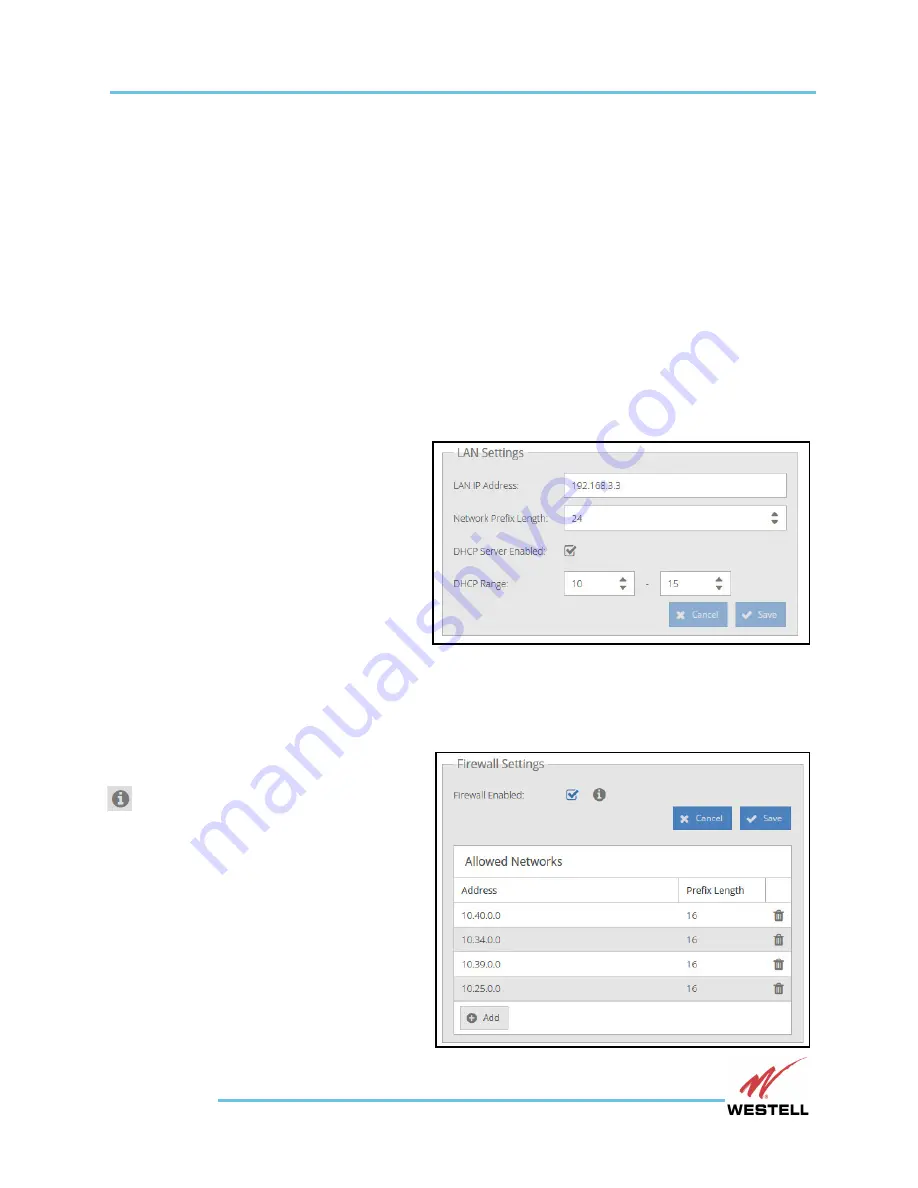
LAN Settings

The 

LAN Settings

 display, shown at right, 

include the 

LAN IP Address

Network 

Prefix Length

, a checkbox to 

enable/disable the 

DHCP Server

, and, when 

the DHCP Server is enabled, a pair of 

windows to set the lower and upper limits 

of 

DHCP Range

.

Important:

If the LAN IP Address is 

changed while the user is 

connected via LAN (as 

opposed to over the modem), the connection to the GUI will be lost and you will 

have to navigate to the new LAN address in a web browser.

Firewall Settings

The 

Firewall Settings

, shown at right, 

include a Firewall Enabled checkbox, an icon 

 to reveal an explanatory tooltip, and a 

list of network addresses allowed by the 

firewall when enabled. The firewall blocks 

all traffic on the modem interface except for 

that originating from or going to the 

Allowed Networks in the specified ranges 

shown in the Firewall Settings
To disable/enable the firewall, 

uncheck/check the Enabled checkbox.

Summary of Contents for RMC-7XX-G

Page 1: ...Westell Technologies April 2016 Part 030 300752 Rev A WESTELL COM INSTALLATION AND WEB UI GUIDE RMC 7XX G Remote Wireless Gateway Installation and Web UI Guide...

Page 2: ...l All other names are trademarks of their respective owners Information is correct at time of publication and is subject to change without notice Contact Westell in Aurora Illinois to verify current p...

Page 3: ...ss Gateway and configure the device using its Web User Interface Guide to this Document Product Components Cautions and Warnings Customer Assistance Required Tools and Materials Device Setup and Insta...

Page 4: ...SMA Female Cellular PCS Antenna Connection SiteBus Connection Future Version Use Battery Input Usage optional in Gateway Bistate Inputs Future Version Use Analog Input and Relay Connections Future Ve...

Page 5: ...ng wrist strap throughout the installation process Environment CAUTION In the event that RMC 7XX G has been subjected to adverse environmental conditions a service inspection of RMC 7XX G should be ma...

Page 6: ...rt or 20 to 60 VDC When using the battery input ensure that the battery configuration usually 24 or 48 Volts matches the input power and polarity provided the unit RMC 7XX G Usage Important RMC 7XX G...

Page 7: ...What happened and what you were doing when the problem occurred How you tried to solve the problem Email Technical Support Email support is available You may send email at any time during the day howe...

Page 8: ...Web UI Guide Customer Assistance WESTELL COM Page 8 1 800 377 8766 Product Documentation You can also access and view the most current versions of Westell s Kentrox product documentation on our web si...

Page 9: ...rist strap Drill Pencil or soft tipped marker PC or laptop set to DHCP Materials Screws sized to fit your base plate Screw head diameter must be larger than 3 16 inch and smaller than 3 8 inch Screw s...

Page 10: ...the screws from the center of each side panel with a screwdriver See Figure 1 Lift the top cover off the unit Figure 1 Cover screw locations on the sides of RMC 7XX G marked in red Note RMC 7XX G Rem...

Page 11: ...cuit board until the hasp is moved back to unlock it Figure 2 The mini SIM card is shown partially inserted into its holder Important Installers might need to move the antenna leads connected to the p...

Page 12: ...or disconnecting devices can occur between the earthed conductor of the in building wireless system repeater and the earthing electrode conductor Run and dress the ground wire to accepted company sta...

Page 13: ...ounted horizontally or vertically inside a case etc 1 Align the slotted screw openings adjoining and perpendicular to the sides of the unit with the properly spaced screw openings on the base plate Th...

Page 14: ...ly 30 seconds The red FLT LED then will flash for approximately 1 minute 45 seconds and then go out The green DC LED should remain illuminated as long as power is applied signifying a successful insta...

Page 15: ...repeaters to RMC 7XX G and allow you to connect RMC 7XX G to a laptop PC or LAN for provisioning and control 1 Use an 8 pin modular plug to 8 pin modular plug straight 100BaseT cable such as Kentrox p...

Page 16: ...will open displaying the login screen shown in Figure 5 Important When using the HTTPS protocol and accessing the web interface for the first time an error page will display indicating that there is...

Page 17: ...te while all the others are gray The name and icon of the screens not presently displayed turn a lighter gray when the user moves the cursor over them Screen Size and Arrangement The Web UI screen wil...

Page 18: ...ettings display showing a single device Device Settings display columns show each device s IP Address Status a Port Settings link and a Description A row is displayed for each device When the user cli...

Page 19: ...s over a status icon Users can update the Status display any time by clicking the device row and then the Update button The status of a newly added offline device will initially appear as Unknown The...

Page 20: ...ttempt to enter an IP address which does not conform to the LAN settings will generate an error message A Description must be entered to add a device An error message will appear if the user attempts...

Page 21: ...Save button Unsaved changes to these settings can be canceled by clicking the X at upper right to close the display Clicking the Add Port button at lower left opens a new bottom row with blank fields...

Page 22: ...rameters are not configurable in this display Contents of All Mapped Ports display columns can be sorted and columns can be concealed and revealed with the column header drop down menus shown in Figur...

Page 23: ...ers selected in supervisor s navigation pane revealing User Settings display Figure 14 User Settings display To add a user click the Add button at lower left The Add User dialog box opens Add the desi...

Page 24: ...d and the drop down menu to reset the user profile as desired Click Save to save the edits or the X at upper right to close the dialog box without saving the changes As with the Add User dialog box th...

Page 25: ...N Settings The LAN Settings display shown at right include the LAN IP Address Network Prefix Length a checkbox to enable disable the DHCP Server and when the DHCP Server is enabled a pair of windows t...

Page 26: ...lick the delete icon at the right end of that network s row A confirm Deletion message will appear click Yes to delete the network or No or the X at upper right to cancel the deletion When a network i...

Page 27: ...h information about the Gateway device and modem This display shows information about the Gateway device and the Modem WAN Address present Signal Strength modem Type Operational State up or down and I...

Page 28: ...ative humidity 0 to 95 non condensing Power Input power 5 watts minimum 12 watts maximum Input voltage range 20 to 60VDC Voltage applications 24VDC and 48VDC Fuse Ratings 0 5 A at 60 VDC Input Output...

Reviews: