Westell ProtectLink VHF-UHF Installation And User Manual Download Page 54

VHF-UHF Bi-Directional Amplifier Installation and Users Guide
Installation Guidelines: 4.10 Connecting to the Alarm Relay Panel

WESTELL.COM

1-800-377-8766

Page 4-12

4.10 Connecting to the Alarm Relay Panel

Use an industry standard multi-conductor alarm cable between 22 and 14 gauge to 
connect the Westell VHF-UHF Bi-Directional Amplifier to an external alarm relay 
panel.

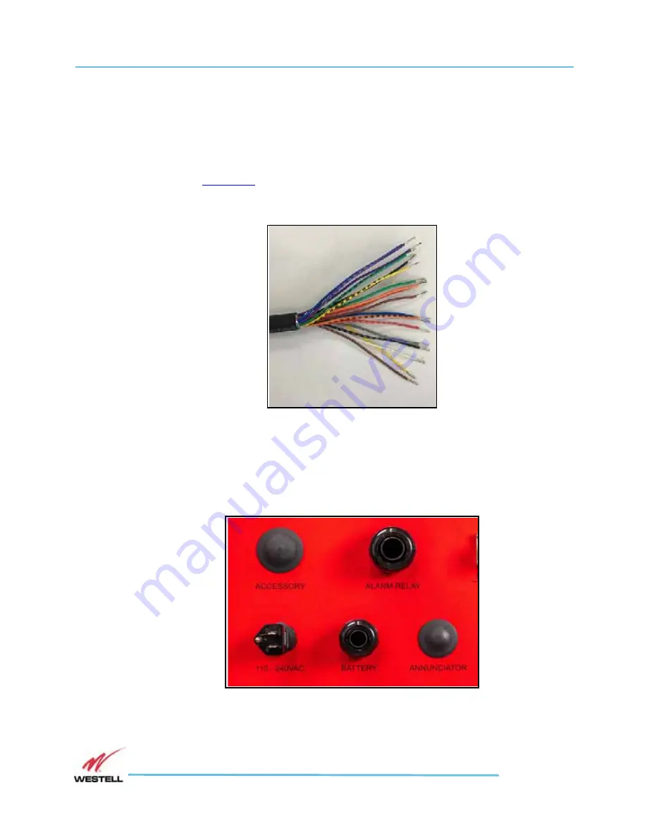
1. Strip the outer serial cable insulation back to expose the inner conductors, as 

shown in 

Figure 4-6

.

2. Strip back the insulation on the ends of each conductor. (Tin wires as needed.)

Figure 4-6   

Stripped alarm wire

3. If using the provided conduit fittings, feed alarm cable through the watertight 

conduit and terminate in an electrical junction box. If using the provided watertight 
cordgrips, remove the conduit fitting from the bottom of the BDA chassis and 
replace with the suitably sized cordgrip fitting.

Figure 4-7   

Conduit fittings and plugged cable ports

Summary of Contents for ProtectLink VHF-UHF

Page 1: ...Software version 1 0 Westell Technologies Part 030 102000 Rev A January 2022 WESTELL COM PRODUCT MANUAL Installation and Users Guide ProtectLink VHF UHF Bi Directional Amplifier...

Page 2: ...and the specific terms of any particular sale apply Westell Inc 750 North Commons Drive Aurora IL 60504 USA Toll Free 800 377 8677 International 1 630 375 4950 Fax 1 630 375 4931 Product Registration...

Page 3: ...cument Purpose and Intended Users 1 2 1 2 Product Application 1 2 1 3 Product Registration Information 1 2 1 4 Safety Guidelines 1 3 1 5 Important Antenna Safety Information 1 5 1 6 FCC Part 90 Signal...

Page 4: ...he VHF UHF Bi Directional Amplifier 4 10 4 9 Connecting the Emergency Power Off Button 4 11 4 10 Connecting to the Alarm Relay Panel 4 12 4 11 Connecting the Power Cable 4 14 4 12 Connecting the Batte...

Page 5: ...Bi Directional Amplifier Installation and Users Guide WESTELL COM 1 800 377 8766 Page TOC 3 A 1 Important Product Information A 2 Appendix B Acronyms and Abbreviations B 1 B 1 Acronyms and Abbreviati...

Page 6: ...VHF UHF Bi Directional Amplifier Installation and Users Guide WESTELL COM 1 800 377 8766 Page TOC 4...

Page 7: ...e VHF UHF Bi Directional Amplifier 3 10 View of the open ProtectLink BDA cabinet 3 11 Signal Booster Mounting brackets circled 4 7 Antenna ports on a 4 port model 4 8 Ethernet Cable 4 10 GUI port for...

Page 8: ...ed 5 13 Alarm History page 5 14 RF Configuration window 5 15 RF Configuration window with Mode wideband selected 5 15 Conducting an isolation test 5 16 RF Configuration page open for editing 5 17 Band...

Page 9: ...s Preface This preface includes the following information about this ProtectLink VHF UHF Bi Directional Amplifier Users Guide Guide to this Preface Document Purpose Scope Audience and References Docum...

Page 10: ...s ProtectLink VHF and UHF band Bi Directional Amplifier Changes that occur after the publishing date may be incorporated by a complete manual revision or as additions Scope Reference this manual when...

Page 11: ...that is crucial to preventing loss of data or damage to hardware or software and actions that could result in equipment failure Important Important messages contain must have information essential to...

Page 12: ...ically left mouse button while the pointer is over the specified location Right click Instructs the user to press the secondary typically right mouse button while the pointer is over the specified loc...

Page 13: ...ation available The versions of hardware and software you are currently running What happened and what you were doing when the problem occurred How you tried to solve the problem Email Technical Suppo...

Page 14: ...VHF UHF Bi Directional Amplifier Installation and Users Guide Preface Customer Assistance WESTELL COM 1 800 377 8766 Page Preface vi...

Page 15: ...nk VHF UHF Bi Directional Amplifier Guide to this Chapter 1 1 Document Purpose and Intended Users 1 2 Product Application 1 3 Product Registration Information 1 4 Safety Guidelines 1 5 Important Anten...

Page 16: ...ireless systems This guide has been written to address the practical concerns of the installer Note In this and other sections the ProtectLink VHF UHF Bi Directional Amplifier is also referred to as t...

Page 17: ...nd wire properly connected The ground wire must be at least 14 AWG and must be connected to the building ground CAUTION Explosive atmospheres To avoid explosion or fire do not operate this product in...

Page 18: ...via the web interface is not permitted for installations requiring full compliance with UL 2524 Refer to the NOTICE TO USERS INSTALLERS AUTHORITIES HAVING JURISDICTION AND OTHER INVOLVED PARTIES insi...

Page 19: ...s must be placed so that under normal conditions personnel cannot come within 60 cm 24 in of any indoor VHF antenna or 80 cm 32 in of any indoor UHF antenna Adhering to this minimum separation will en...

Page 20: ...an FCC license or express consent of an FCC License to operate this device When commissioned with filters wider than 75KHz you must register class B signal boosters as defined in 47 CFR 90 219 online...

Page 21: ...ion 1 7 Product Labels WESTELL COM 1 800 377 8766 Page 1 7 1 7 Product Labels FCC and Product Label Placement Figure 1 1 is a right side view of the ProtectLink showing placement of FCC and Product la...

Page 22: ...k VHF UHF Bi Directional Amplifier as shown in Figure 1 1 on page 1 7 Figure 1 2 FCC warning labels on signal booster Product Labels Product labels similar to those shown in Figure 1 3 and Figure 1 4...

Page 23: ...affixed to the ProtectLink VHF UHF Bi Directional Amplifier remote annunciator as shown in Figure 1 1 on page 1 7 Figure 1 5 BDA Remote Annunciator product label This label includes the remote annunci...

Page 24: ...nal Amplifier Installation and Users Guide General Information 1 7 Product Labels WESTELL COM 1 800 377 8766 Page 1 10 The fuse warning label below is affixed to the internal fuse cover plate see Figu...

Page 25: ...2 This chapter provides an overview of the Westell ProtectLink VHF UHF Bi Directional Amplifier Guide to this Chapter 2 1 Product Information 2 2 Product Features 2 3 Included Accessories 2 4 Optional...

Page 26: ...ired The external antenna is typically directional such as a Yagi or Panel antenna Internal antennas are typically omnidirectional although various other types may be used depending on the coverage ap...

Page 27: ...otection Under over voltage protection Fault protection Low power consumption Redundant power supplies operates on 120VAC or 24VDC Built in battery backup and alarming SNMP Web based GUI Built in Annu...

Page 28: ...377 8766 Page 2 4 2 3 Included Accessories Table 2 1 contains the items that are shipped with the ProtectLink VHF UHF Bi Directional Amplifier Table 2 1 Included Accessories Quantity Description 1 AC...

Page 29: ...connectors 138 960 MHz CS05 525 614 VHF PT7 138 960 N f 7dB Power Tapper Public Safety grade 200W N connectors 138 960 MHz CS05 526 614 VHF PT8 138 960 N f 8dB Power Tapper Public Safety grade 200W N...

Page 30: ...t ProtectLinkClass A B and PS Enhanced series class B BDAs CS19 PYL12V45FS CS19 PYL12V45FS 12VDC 45 AH Battery for BBC 003 2 required CS19 PYL12V100FT CS19 PYL12V100FT 12VDC 100AH Battery for BBC 003...

Page 31: ...l drawing of your Westell ProtectLink VHF UHF Bi Directional Amplifier Guide to this Chapter 3 1 RF Specifications 3 2 Power and Fuse Specifications 3 3 Mechanical Specifications 3 4 Environmental Spe...

Page 32: ...rs per Band 16 4 Number of UL Class A Filters per Band 16 5 Class A Channelized Filter BW 12 5 25 50 75 kHz Default 75 kHz with minimum group delay 6 Class A Filter Rejections dB f is rejection from B...

Page 33: ...377 8766 Page 3 3 7 Class A System Group Delay for each filter uS TOTAL DL group delay between DONOR and SERVICE ports 12 5 kHz 60 Will not meet P25 phase 1 or 2 requirements 25 kHz 36 P25 phase 1 co...

Page 34: ...hout duplexer filters 9 System Gain UL 85 dB Without duplexer filters 10 UL and DL Composite Gain Adjustment 30 dB 1 dB steps 11 UL and DL Attenuation per Filter 30 dB 1 dB steps Attenuation aka Gain...

Page 35: ...ced only with 5x20mm 2 5A fuses such as Littelfuse 0234 series part 2 5P See 5 10 Fuse Replacement on page 5 31 Table 3 2 Power Specifications Parameter Specification Main Power Input Voltage 120 240...

Page 36: ...5 lbs 36 1 kg BDA cabinet without filters Connectors Donor Coverage Antenna Ports N AC Power In 8402 Gland Connector Open Wire Terminal DC Battery Power In 8402 Gland Connector Open Wire Terminal Acce...

Page 37: ...7 3 4 Environmental Specifications Table 3 4 lists environmental specifications for the ProtectLink VHF UHF Bi Directional Amplifier Table 3 4 Environmental Specifications Parameter Specification Not...

Page 38: ...orrectable oscillation detected that a reduction in gain could not resolve causing RF shutdown RF EMITTER FAIL OSCILLATION RF SHUTDOWN Oscillation Detected Warning SYSTEM COMPONENT FAIL OSCILLATION RE...

Page 39: ...3 6 Product Appearance Figure 3 1 shows the external configuration of your ProtectLink BDA Figure 3 1 External configuration of the VHF UHF Bi Directional Amplifier BOTTOM RIGHT SIDE VIEW 20 in 508 mm...

Page 40: ...of the VHF UHF Bi Directional Amplifier in Figure 3 2 Figure 3 2 Bottom views of the VHF UHF Bi Directional Amplifier Bottom Panel Feedthroughs and Connectors On the bottom of the ProtectLink BDA are...

Page 41: ...OM 1 800 377 8766 Page 3 11 Label Placement Label placement on the VHF UHF Bi Directional Amplifier is shown in Figure 1 1 on page 1 7 Figure 3 3 View of the open ProtectLink BDA cabinet Reset Alarm C...

Page 42: ...VHF UHF Bi Directional Amplifier Installation and Users Guide Specifications and Product Appearance 3 6 Product Appearance WESTELL COM 1 800 377 8766 Page 3 12...

Page 43: ...ntenna Installation Guidelines 4 4 Determining cable entry selection 4 5 Mounting and Grounding the ProtectLink BDA 4 7 Verifying the Physical System Setup 4 8 Controlling the VHF UHF Bi Directional A...

Page 44: ...nit is for installation in a locked room such as a fire control room a locked enclosure or an equivalent enclosure that requires a tool to open DANGER Refer to the 1 3 Safety Guidelines section for pr...

Page 45: ...o installation WARNING Lifespan and performance of the Signal Booster may be reduced if the unit is operating outside its nominal temperature range CAUTION When the Signal Booster is in operation RF f...

Page 46: ...the donor pass above the location s of the service antennas Normally the service antennas are installed behind and below the donor antenna as viewed from above This approach helps avoid interference...

Page 47: ...ount the indoor antennas away from areas where mobile subscribers frequently use their radios fire alarm control rooms or dispatch areas Note If the signal level from antenna at the UL service port is...

Page 48: ...rips For a cleaner installation conduit is preferred and those fittings come preinstalled on the BDA UL2524 Installations require the use of the conduit fittings If you wish to use the cordgrips for a...

Page 49: ...r mounting bracket See Figure 4 1 2 Move the ProtectLink BDA and drill the mounting holes at the marks in the wall 3 Install a wall anchor 8mm x100mm in each of the eight 8 drilled holes 4 Install the...

Page 50: ...put Figure 4 2 Antenna ports on a 4 port model Antenna port connections are listed in Table 4 1 below Table 4 1 Antenna Port Connections Model Port Connects to 4 Port Models DONOR DL INPUT Rooftop don...

Page 51: ...k all cables for shorts and opens Verify that there are no cables with loose or poor connections RF leakage could cause oscillation to occur under some conditions If the rooftop antenna donor antenna...

Page 52: ...ured computer with a web browser is connected via an Ethernet cable such as the one shown in Figure 4 3 During installation or maintenance the Network Interface port of a computer can temporarily be c...

Page 53: ...allow for a remote Emergency Power Off EPO switch to disable all RF functions of the ProtectLink BDA See Figure 4 5 below Figure 4 5 Emergency Power Off connections Use a mushroom type EPO button ava...

Page 54: ...ay panel 1 Strip the outer serial cable insulation back to expose the inner conductors as shown in Figure 4 6 2 Strip back the insulation on the ends of each conductor Tin wires as needed Figure 4 6 S...

Page 55: ...ure 4 8 BDA Alarm Relay terminals 5 Connect the stripped end of the serial cable to the alarm relay panel Refer to Table 4 2 below for connection information Table 4 2 Alarm Connections Alarm Descript...

Page 56: ...nduit fitting preinstalled in the 100 240VAC port and the AC cord exiting that fitting You may need to disconnect the AC cord from the terminal fittings in the BDA to route through 1 2 conduit or repl...

Page 57: ...uide Installation Guidelines 4 11 Connecting the Power Cable WESTELL COM 1 800 377 8766 Page 4 15 3 Screw the connector on securely 4 When the Signal Booster is properly set up and ready to have power...

Page 58: ...2 and leads which connect to the signal booster s battery terminals as shown in Figure 4 11 below Refer to CS19 BBC 003 installation instructions Figure 4 11 Battery cable connections to signal booste...

Page 59: ...nce Considerations CAUTION Do not wear conductive jewelry or use conductive tools while cleaning and working near battery terminals Batteries should be marked with their installation date upon install...

Page 60: ...emote Annunciator connects to the BDA with a standard Ethernet cable housed in conduit meeting specified standards Follow these steps 1 Install the annunciator base on a wall mounted junction box at t...

Page 61: ...atures Guide to this Chapter 5 1 Controls Inside the ProtectLink BDA 5 2 Accessing the ProtectLink BDA GUI 5 3 Web GUI System Status Display 5 4 BDA Alarms Page 5 5 RF Configuration 5 6 System Setting...

Page 62: ...F power switch and a reset button These and other interior features are shown in Figure 5 1 below Figure 5 1 ProtectLink BDA interior features ON OFF Switch The red ON OFF switch above the AC power co...

Page 63: ...nct functions A momentary press will temporarily disable the audible annunciator in the BDA and on the remote annunciator if one is installed After 24 hours the audible alarms will be re enabled A pre...

Page 64: ...DA ships with the IP address 192 168 1 150 on the GUI port To connect directly to the BDA from a laptop or PC with a CAT 5E cable or over a LAN change the TCP IP settings on your computer to enable a...

Page 65: ...appears as shown in Figure 5 3 below Figure 5 3 Sign In screen Sign in the first time with the default user name admin and default password admin The System Status screen will appear as shown in Figu...

Page 66: ...as shown in Figure 5 4 below Key features numbered in Figure 5 4 are described in Table 5 1 Current Alarms are color coded as described in Table 5 2 on page 5 9 Figure 5 4 Web GUI System Status Screen...

Page 67: ...RF Configuration on page 5 15 7 System Settings Click to open the System Setting page See 5 6 System Settings Page on page 5 21 8 Backup Configuration Click to open the Backup Configuration popup win...

Page 68: ...tallation and Users Guide System Operation 5 3 Web GUI System Status Display WESTELL COM 1 800 377 8766 Page 5 8 Figure 5 5 CONTACT and HELP popups with QR codes Scan or click QR code to open new brow...

Page 69: ...ng Click an alarm indicator once to display a popup revealing a more detailed alarm description and or indicators for multiple alarm sources as shown in Figure 5 7 Double click an alarm indicator to a...

Page 70: ...multiple alarm sources Either double click an alarm indicator shown in Figure 5 6 or click a popup indicator as shown in Figure 5 7 to reveal that alarm source s Mask Delay and Frequency settings appe...

Page 71: ...ACITY Low battery capacity at 70 reduction BATTERY CHARGER Battery Disconnection or Battery Not Charging status EMERGENCY POWER OFF Emergency Power Off has been activated externally DOWNLINK AMPLIFIER...

Page 72: ...s To edit an alarm follow these steps 1 Click the EDIT ALARMS button to open the ALARM CONFIGURATION popup 2 Double click on the first alarm you want to edit Activate the tools to adjust settings as s...

Page 73: ...he MASK ALL ALARMS button The MASK ALL CONFIGURATION display will appear as shown at right Click MASK to mask all alarms the BDA Alarms page will update with all indicators masked as shown in Figure 5...

Page 74: ...t the user set the number of rows displayed per page and scroll through multiple pages Click the CLEAR ALARM HISTORY button to empty the alarm log Click the EXPORT ALARM HISTORY button beneath the log...

Page 75: ...RATION button on the System Status page opens the RF Configuration window shown in Figure 5 12 below Features of the Band Settings are detailed in below Features of the Filter Settings are detailed in...

Page 76: ...open showing progress and within a few seconds a message that the test succeeded and the maximum safe gain level Do not exceed this gain level when commissioning the BDA without first making adjustmen...

Page 77: ...ng as shown in Figure 5 15 below Figure 5 15 RF Configuration page open for editing RF Configuration Page Features Two rows of band settings are displayed in the upper part of the RF Configuration pag...

Page 78: ...ain 85 dB DL 85 dB UL Squelch Displays DL top and UL Squelch settings Adjustable from 90 to 50 dBm DL and UL Click in a value field to edit the setting Check the checkbox to activate Squelch Note When...

Page 79: ...he RF CONFIGURATION popup shown at right The filter settings open for editing as shown in Figure 5 18 When editing is complete click APPLY Figure 5 18 Filter settings open for editing Table 5 5 RF Con...

Page 80: ...d Simplex models UL and DL settings are automatically duplicated VHF Duplex and 4 Port Simplex models UL and DL Center Frequencies are independent See the product description under SYSTEM INFORMATION...

Page 81: ...s This page also displays product model number product description serial number uptime timer and firmware version Click the SYSTEM SETTINGS button on the System Status page to open the SYSTEM SETTING...

Page 82: ...mplifier Installation and Users Guide System Operation 5 6 System Settings Page WESTELL COM 1 800 377 8766 Page 5 22 Figure 5 20 System Settings page opened for editing Figure 5 21 Date picker popup f...

Page 83: ...or click the calendar icon to open the date picker popup as shown in Figure 5 21 Add minutes and seconds in place of 00 00 to advance the clock by a specified period The clock display stops while in e...

Page 84: ...DDRESS Static IP address of GUI port preset to 192 168 1 150 SUBNET MASK GUI connection subnet mask System Information fields PRODUCT MODEL DESCRIPTION including UHF or VHF service SERIAL NUMBER GUI V...

Page 85: ...ATION buttons Backup Configuration To save the current signal booster configurations as the backup configuration click the BACKUP CONFIGURATION button The BACKUP CONFIGURATION popup shown at right app...

Page 86: ...Figure 5 22 SNMP Trap Receivers page Click the button at upper left to add a new SNMP trap receiver The ADD SNMP TRAP RECEIVER popup shown in Figure 5 23 appears Add the trap IP address in the HOST fi...

Page 87: ...ay The DELETE SNMP TRAP RECEIVER popup window appears as shown at right Click DELETE to confirm the deletion The SNMP TRAP RECEIVERS page refreshes and the just deleted receiver is no longer shown Cli...

Page 88: ...appears green when the unit is on and turns dark gray when off The button also says whether the receiver is on or off Edit the Port number Edit the VERSION using the drop down menu Version v2c is use...

Page 89: ...th toggle buttons to DISABLE or ENABLE the BDA horn Disabling the horn will silence the audible alarm in the BDA enclosure Click APPLY to activate the configuration CAUTION Permanent alarm silencing v...

Page 90: ...TELL COM 1 800 377 8766 Page 5 30 will appear with a timer showing when the test will end The user can click the END TEST button to halt the test at any time Click the TEST ALL button to test all of t...

Page 91: ...Beneath this cover are fuses F1 which powers the Remote Annunciator and F2 which powers the head end DAS optical master unit To replace fuses follow these steps 1 Disconnect power to the BDA 2 Unscrew...

Page 92: ...VHF UHF Bi Directional Amplifier Installation and Users Guide System Operation 5 10 Fuse Replacement WESTELL COM 1 800 377 8766 Page 5 32...

Page 93: ...PTER 6 This chapter provides software upgrade information for your Westell VHF UHF Bi Directional Amplifier Guide to this Chapter 6 1 Upgrading the System Software 6 2 System Reboot and Factory Reset...

Page 94: ...ll commence A series of color coded status messages such as those at right will appear as the upgrade proceeds saying SYSTEM UPGRADE has started status is uploading then SYSTEM UPGRADE is in progress...

Page 95: ...which can be rebooted the user must select the desired device with the selection menu Click SYSTEM REBOOT to proceed with the reboot When the BDA is rebooted service will be disrupted during the reboo...

Page 96: ...VHF UHF Bi Directional Amplifier Installation and Users Guide System Software Upgrade 6 2 System Reboot and Factory Reset WESTELL COM 1 800 377 8766 Page 6 4...

Page 97: ...ESTELL COM APPENDIX A Important Product Information This appendix includes important information about your ProtectLink VHF UHF Bi Directional Amplifier Guide to this Appendix A 1 Important Product In...

Page 98: ...1 1 on page 1 7 See 1 3 Product Registration Information on page 1 2 A 1 2 NRTL This product is NRTL listed A 1 3 Configuration List The table below lists variants of the Westell VHF UHF Bi Direction...

Page 99: ...Page B 1 WESTELL COM APPENDIX B Acronyms and Abbreviations This chapter provides information on acronyms and abbreviations used in this document Guide to this Appendix B 1 Acronyms and Abbreviations...

Page 100: ...rrent AGC Automatic Gain Control COM Communications dB Decibels dBi Decibels relative to isotropic dBm The power ratio in decibels dB of the measured power referenced to one milliwatt mW DC Direct Cur...

Reviews: