Section DSA-WM2-140-202
030-101674 Rev. A
R
5
0803I2RA
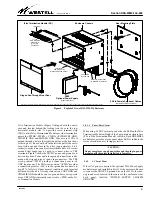
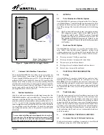
Figure 4. Exploded View of DSAWM-214 Enclosure
Rear Mounting Plate
50-Pin Female Amphenol Cables
(Optional Facility Connections)
Enclosure Chassis
Chassis #6
Ground Lug
Hinged See-Through Front Door
14 Slots for
(or seven 400-Type Cards)
200-Type Cards
Telco Termination Module (DC)
(Provided)
Customer Connections
via RJ48C/H Connectors
Enclosure is shipped full-assembled. This view separates the rear mounting plate and the front door from the enclosure for visual clarity.
Optional Power Supply
(Plugs into Slot 15)
J1 - J14
(6-Pin Wirewrap
Connectors)
for Facility
Connection
2555
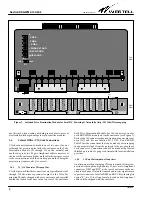
Telco Termination Module
(Figure 7) shipped with the enclo-
sure and located behind the locking front door in the top,
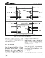
horizontal module slot. A 6-position screw terminal strip
(TB1) on this Telco Termination Module provides termination
points for -PWRB, -PWRA, +PWRA, +PWRB/CKT GND,
CHASSIS GND and SHIELD GND. Wire access to TB1 is
gained through a hole in the right side wall near the front door
or through a ½" knock-out hole in the left side wall of the enclo-
sure. Allow enough slack in the wires (approximately 6 to 8
inches) to easily remove and (re)insert the module. It is recom-
mended that spade lugs be used to connect wires to TB1
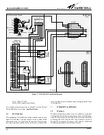
terminals. Figure 7 shows the TB1 DC power and ground con-
nection locations. Power and return ground connections can be
made with stripped wire or spade lug connectors. The TB1
screw position -PWR" provides a connection point to -48
VDC input power. The TB1 screw poPWR" provides
a connection point for -48 V return or ground and connects to
pin #17 of all slots. Under normal conditions, each terminal
will draw less than 0.6 A steady state current. CKT GND and
CHASSIS GND should be run to a ground buss over separate
wires. CKT GND is internally connected to +PWR on the
Tel-
co Termination Module
.
3.4.1.1
Power/Fuse Alarm
When using -48 VDC external power, the red LED on the
Telco
Termination Module
will light if the 2-amp main enclosure fuse
(F1 on
Telco Termination Module
) is blown. Each DNI/HDSL
module also provides a front panel alarm LED to indicate the
status of each module’s fusing protection.
- CAUTION -
Do not energize or supply power through the plug-in power
module until the entire installation is complete.
3.4.2
AC Local Power
If local AC power is desired, the optional 2555 Power Supply
module is used and installed in Slot 15 of the enclosure. Be sure
to connect the GRN/YEL ground wire on the 2555 to the chas-
sis ground screw located in the center of the enclosure’s rear
back panel, labelled POWER SUPPLY CHASSIS
GROUND".


