background image

Section DSA-WM2-140-202

030-101674 Rev. A

R

8

0803I2RA

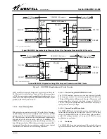
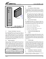
Figure 7.    Included Telco Termination Module for Local DC  Powering & Network/Facility (CO Side) Wirewrapping

Top

View

Front

View

POS

 1

P4

P3

P2

- PWRA

+ PWRA

+PWRB/CKT GND

CHASSIS GND

SHIELD GND

TB1

THRU

OPEN

S1

LD1

ON

1

SGND

NC

R1

T1

R

T

SGND

NC

R1

T1

R

T

SGND

NC

R1

T1

R

T

SGND

NC

R1

T1

R

T

SGND

NC

R1

T1

R

T

SGND

NC

R1

T1

R

T

SGND

NC

R1

T1

R

T

SGND

NC

R1

T1

R

T

SGND

NC

R1

T1

R

T

SGND

NC

R1

T1

R

T

SGND

NC

R1

T1

R

T

SGND

NC

R1

T1

R

T

SGND

NC

R1

T1

R

T

SGND

NC

R1

T1

R

T

POS

 2

POS 3

POS 4

POS 5

POS 6

POS 7

POS 8

POS 9

POS 10

POS 1

1

POS 12

POS 13

POS 14

1
2

P6

1
2

P3

1
2

P1

2 AMP

ALARM

1

6

- PWRB

Pin 1

Pin 6

use this jack when working with plug-in modules to prevent
electrostatic discharge damage to static-sensitive modules.

3.6

Central Office (CO) Side Connections

CO side connections can be made in one of two ways. One way
is through the wirewrap pins inside the enclosure on the Telco
Termination Module (J1 through J14 on the module) and
another way is by two 25-pair Amphenol cable connectors at
the rear of the enclosure. Either method limits customer access
to these connections, with the wirewrap pin method being the
most secure (requires a key for access).

 3.6.1

J1 - J14 Connector Wirewrap Pins

CO side (network/facility) connections are typically made to J1
through J14, the wirewrap connector pins on the Telco Ter-
mination Module shipped with every enclosure and installed
behind the locked front door in the top slot of the enclosure.

Each Telco Termination Module has 14 J-connectors, one for
each DNI/ HDSL module slot in the enclosure (see Figure 7).
Each of the 14 J-connectors has six wirewrap pins; one pin is not
used (NC) and five are labelled R1, T1, R, T, and SGND.
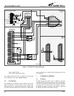
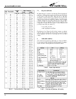
Table 2 lists the connections that can be made by wirewrapping
the appropriate leads from the network to the proper pins of
each connector. Connections should be made using twisted
shielded pair cable of a gauge consistent with local installation
practices.

 3.6.2

25-Pair Male Amphenol Connectors

An alternate method of making CO side (network/facility) con-
nections is through the high-density, 25-pair, male, Amphenol
connectors, XMT and RCV, at the rear of enclosure on the en-
closure back panel. Network transmit and receive signals are in
separate connectors, labelled XMT and RCV. By ordering list
option S", two 15-foot long, female-to-stub-ended Amphenol
cables will be shipped with the enclosure.

Summary of Contents for DSAWM-214ALCI2

Page 1: ...Office CO side connections are made via wirewrap pins mounted on the plug in Telco Termination Mod ule located at the top of the enclosure or via two 50 pin Amphenol type connectors at the top rear of...

Page 2: ...ded that adequate horizontal and vertical space be left between multiple installations to allow for proper cable access and ven tilation The distance from the cable entry point should be consistent wi...

Page 3: ...nnections 3 1 2 2 Local Powering Mode When local power mode is selected TB1 on the Telco Termina tion Module provides screw terminals for 48 V battery PWR position and 48 V return PWR position A separ...

Page 4: ...ck plate from the enclosure by depressing the black metal push buttons located near the bottom on each side of the enclosure 2 Lift and place the back plate on the wall in the desired mounting locatio...

Page 5: ...om mended that spade lugs be used to connect wires to TB1 terminals Figure 7 shows the TB1 DC power and ground con nection locations Power and return ground connections can be made with stripped wire...

Page 6: ...but not factory installed for optional installation between the CHASSIS GND and CKT GND terminals on TB1 for applications re quiring chassis ground to be connected to circuit ground 3 5 2 Circuit Gro...

Page 7: ...de with stripped wire or by spade lug connectors TB1 screw position PWR is the battery return TB1 screw position CKT GND provides cir cuit ground as described in Paragraph 3 5 2 TB1 screw position CHA...

Page 8: ...access to these connections with the wirewrap pin method being the most secure requires a key for access 3 6 1 J1 J14 Connector Wirewrap Pins CO side network facility connections are typically made to...

Page 9: ...le is the following option S1 This 2 position slide switch provides a shield ground from TB1 connected to pins 7 and 8 of the RJ48C jacks J1 through J14 with S1 in the THRU position The shield ground...

Page 10: ...9 14 55 49 T R J16 Voice 800 377 8766 email global_support westell com For additional information about Westell visit the Westell World Wide Web site at http www Westell com 6 2 Part Numbers This equi...

Page 11: ...W O T1 41 4 R BR SGND 1 SGND 1 NC 2 NC 2 R 13 5 O W R 13 5 BR R T 7 6 W O T 7 6 R BR 3 R1 47 POS 3 3 G W 10 R1 47 POS 10 3 S R T1 41 4 W G T1 41 4 R S SGND 1 SGND 1 NC 2 NC 2 R 13 5 G W R 13 5 S R T 7...

Page 12: ...n the defective unit freight prepaid along with a brief problem description to the address we will provide to you when you contact us Voice 630 375 4211 email rgmdept westell com Replacements are ship...

Reviews: