background image

10

O

PERATION

(

CONTINUED

)

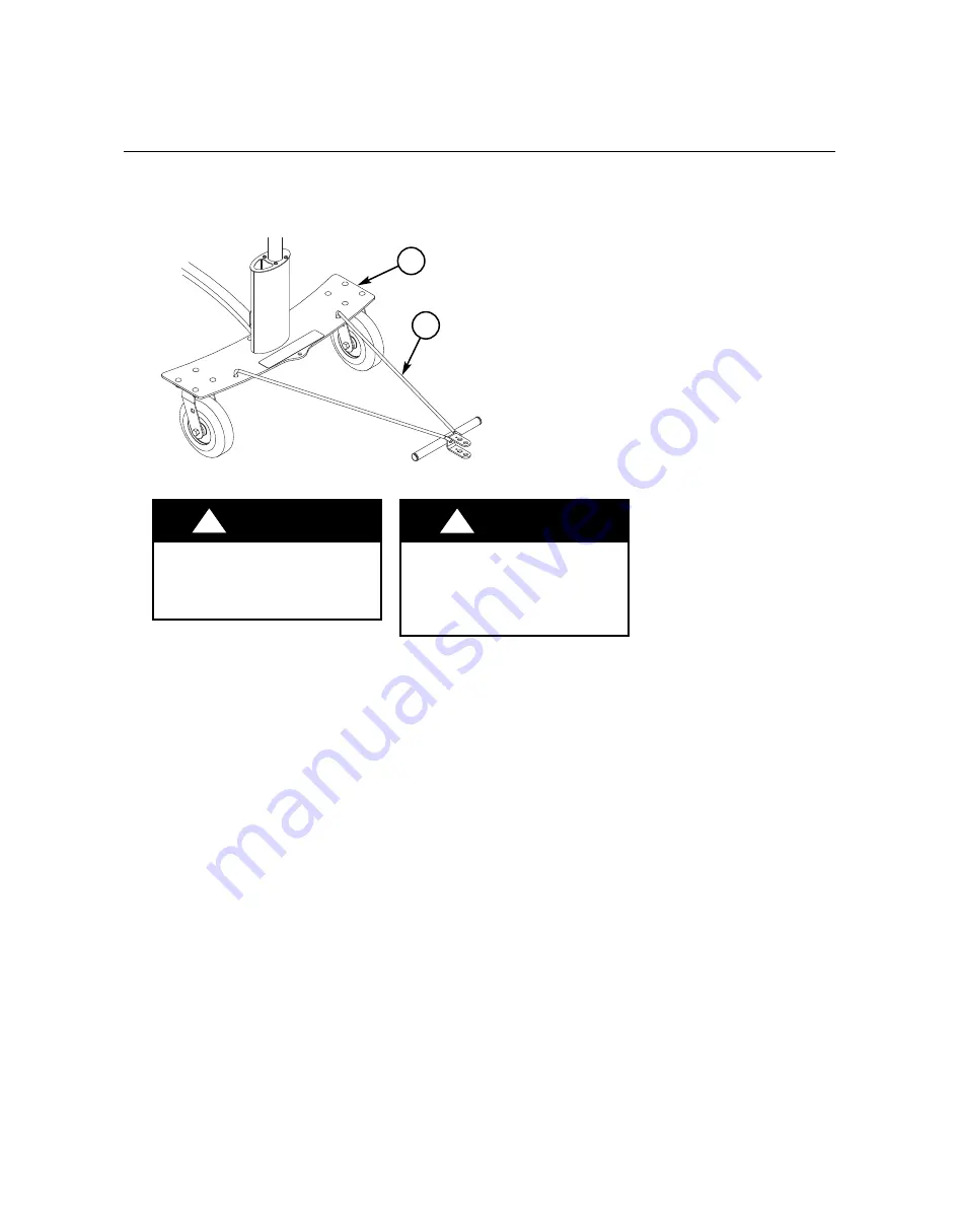
4.   A separate tow bar (#4) is provided that inserts into two holes in the percussion cart base (#1).  

The tow bar (#4) may also be used as a handle to pull the Percussion Cart manually or can be

attached horizontally to a lawn and garden tractor. 

(Detail B)

5. When the tow bar is removed, store it out of the way so that it is not an obstruction or hazard.
6. If the Percussion Cart is transported in a vehicle, it must be braced or strapped to the vehicle so 

that it cannot move.  Bracing must use tie-downs or straps specifically designed to prevent the

Percussion Cart from moving in the vehicle.  Remove objects or instruments that may be damaged

during transport.  Secure Percussion Cart at the lower frame.  Pads or other protection against

abrasion may be required.  

4

Detail B

When towing the Percussion

Cart do not exceed 5 mph or

tow more than three carts

together. 

!

CAUTION

When towing the Percussion

Cart, avoid tight turns which

may result in the tow vehicle

making contact with the cart

or tow bar.

!

CAUTION

Summary of Contents for OnBoard Percussion Cart

Page 1: ...corp com Note Please read and understand these instructions before assembly or use Note Remove all items from the shipping cartons and arrange them in a convenient location Refer to the illustrations on the following pages If you need additional information contact the Wenger Corporation using the information below Important User Information 2 Safety 3 Tools Required 4 Fastener List 4 Parts List 5...

Page 2: ...or for direct indirect special incidental or consequential damages resulting from the use or defect of this manual The information in this document is not intended to cover all possible conditions and situations that might occur The end user must exercise caution and common sense when assembling or installing Wenger Corporation products If any questions or problems arise call Wenger Corporation at...

Page 3: ...wly up or down a ramp with the narrow end of the cart in the direction of travel Do not pull or push too high on the cart or pull or push on the sides of the cart which may cause the cart to tip over Avoid off center loads which may cause the cart to tip over Because swivel casters move in any direction the operator must move the cart slowly and have a clear view to avoid obstructions and individu...

Page 4: ...Wrench or 9 16 Socket with Ratchet 1 2 Wrench or 1 2 Socket with Ratchet 3 16 Allen Wrench provided Note Extra hardware can be discarded Socket Screw 5 16 18 x 3 Lock Nut 3 8 16 Carriage Bolt 3 8 16 x 1 Nylon Lock Nut 5 16 18 10 11 12 13 ...

Page 5: ...Description Item Description 1 BASE ASSEMBLY 6 MOUNT ASSEMBLY 2 SWIVEL CASTER 7 SUPPORT WELDMENT 3 RIGID CASTER 8 TUBE CLAMP EXTRUSION 4 TOW BAR 9 ACCESSORIES CLAMP EXTRUSION 5 CURVED TUBE EXTRUSION 1 7 2 3 4 8 5 6 5 9 ...

Page 6: ... or rigid must be assembled to each base assemblies 3 Align the rigid casters 3 with the bolt holes on the remaining base assembly 1 4 Repeat step 2 ASSEMBLE THE SUPPORT 7 TO THE BASE ASSEMBLIES 1 5 Lay the base assemblies on end 6 Align the cross member 7 to the bolt holes located on inside the base assemblies Detail B 7 Secure the support to the base assemblies using carriage bolt 3 8 16 x 1 10 ...

Page 7: ... extrusion onto the clamps located at the top of the base assemblies 1 Be sure to center the curved tube extrusion so it is evenly positioned on the base units Detail C 9 Place the accessory clamp extrusion 9 parallel to the clamp located on the base assembly 10 Using socket screw 5 16 18 x 3 12 and nylon lock nut 5 16 18 13 tighten the tube clamp extrusions together securing the curved tube extru...

Page 8: ...art To attach the percussion mount assembly Detail D 11 Place the percussion mount assembly 6 and tube clamp extrusion 8 parallel to each other at the desired location on the curved tube extrusion 5 12 Insert the socket screw 5 16 18x3 12 into the percussion mount assembly 6 and through the tube clamp extrusion 8 13 Using the lock nut 5 16 18 13 tighten the percussion mount assembly 6 onto the cur...

Page 9: ...sh at about waist level or lower Pushing above the main support bar can tip the Percussion Cart over Detail A 3 If the Percussion Cart is heavily loaded two people should always work together to move the cart in the direction of travel that the rigid casters can move freely One person pushing at the rear and one person guiding at the front Take care to avoid stationary objects or people standing i...

Page 10: ... a vehicle it must be braced or strapped to the vehicle so that it cannot move Bracing must use tie downs or straps specifically designed to prevent the Percussion Cart from moving in the vehicle Remove objects or instruments that may be damaged during transport Secure Percussion Cart at the lower frame Pads or other protection against abrasion may be required 1 4 Detail B When towing the Percussi...

Page 11: ...ing products 2 Immediately replace any caster wheels that do not rotate or turn freely 3 Immediately replace or repair any tire that develops a flat area 4 Recommended tire pressure is 50 psi Do not exceed the maximum tire pressure shown on the sidewall of the tire 5 During heavy usage periodically check and tighten item 4 for the clamp extrusions holding the curved extrusion 6 Check all fasteners...

Page 12: ... LOCK NUT 5 16 18 3 RIGID CASTER 9 DIAMETER 14 SELF TAP SCREW 1 4 20x3 4 TORX 4 TOW BAR 15 EXTRUSION CAP 5 CURVED TUBE EXTRUSION 16 UPRIGHT EXTRUSION 6 PERCUSSION MOUNT ASSEMBLY 17 WENGER ONBOARD DECAL 7 PERCUSSION CART SUPPORT 18 PLUG 2 00 BLACK 8 TUBE CLAMP EXTRUSION 19 LOCK WASHER 1 4 9 SOCKET SCREW 1 2 13x1 20 SELF TAP SCREW 1 4 20x1 1 4 10 CARRIAGE BOLT 3 8 16x1 21 ACCESSORY CLAMP EXTRUSION 1...

Reviews: