background image

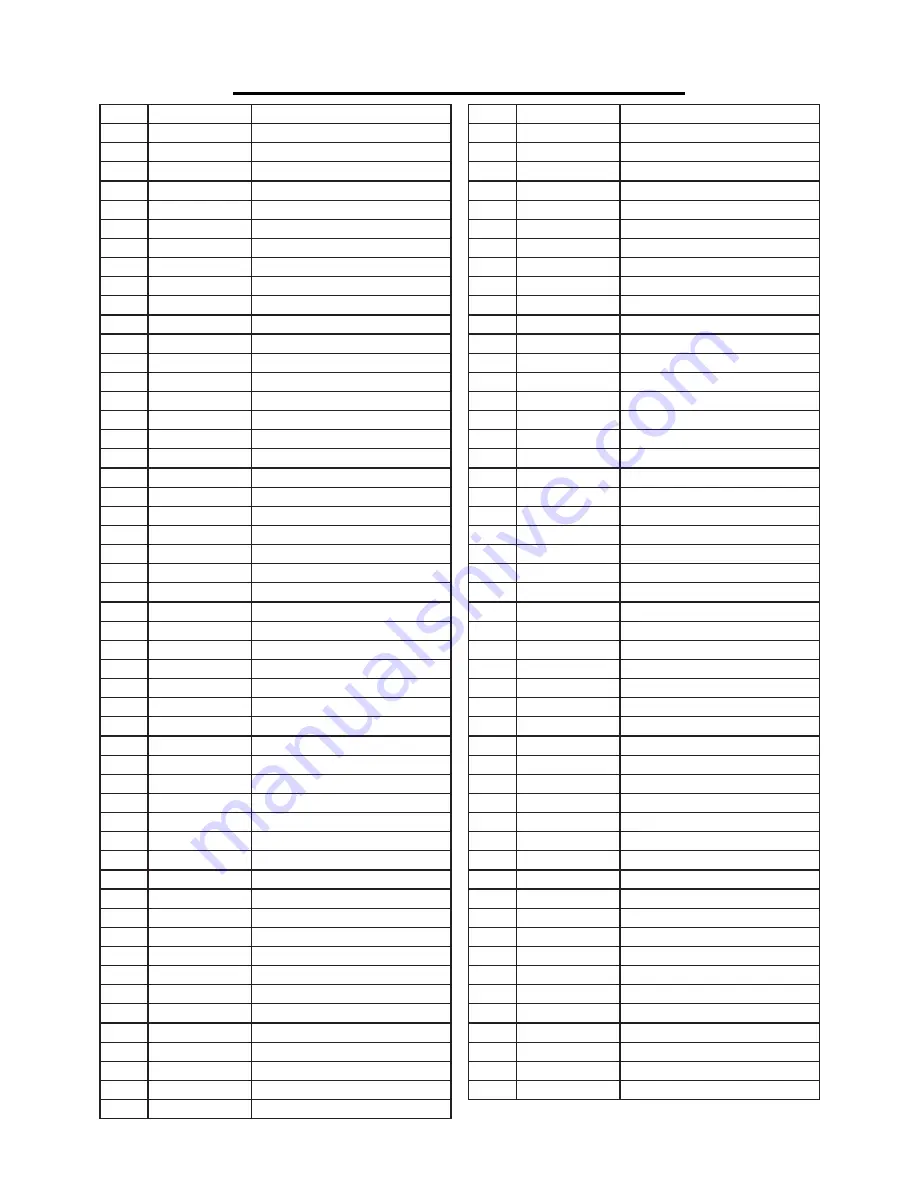
EXPLODED VIEW & PARTS LIST

No. 

Part No.

Description

1

61731-001

Screw

2

61731-002

Washer

3

61731-003

Bushing

4

61731-004

Exhaust Cap

5

61731-005

Washer

6

61731-006

Screw

7

61731-007

Washer

8

61731-008

Cylinder Cap

9

61731-009

Cylinder Cap Seal

10

61731-010

Washer

11

61731-011

Valve Seat

12

61731-012

Valve Spring

13

61731-013

O-Ring

14

61731-014

O-Ring

15

61731-015

Valve

16

61731-016

Screw

17

61731-017

Cylinder Seal

18

61731-018

Collar

19

61731-019

O-Ring

20

61731-020

Piston Assembly

21

61731-021

Cylinder

22

61731-022

O-Ring

23

61731-023

O-Ring

24

61731-024

Restrictive Seal

25

61731-025

O-Ring

26

61731-026

Bumper A

27

61731-027

Bumper B

28

61731-028

Body

29

61731-029

O-Ring

30

61731-030

Nose

31

61731-031

Washer

32

61731-032

O-Ring

33

61731-033

Bar Guide

34

61731-034

Pin

35

61731-035

Angle Adjustment Pin

36

61731-036

Spring

37

61731-037

Screw

38

61731-038

Washer

39

61731-039

Safety Bracket A

40

61731-040

Coil Spring Base

41

61731-041

Screw

42

61731-042

Safety Bracket B

43

61731-043

No Mar Tip

43-1

61731-043-1

No Mar Tip Clasp

44

61731-044

Safety Guide

45

61731-045

Pin

46

61731-046

Washer

47

61731-047

Screw

48

61731-048

Spring

49

61731-049

Split Washer

50

61731-050

Rotating Knob Bushing

51

61731-051

Trigger

No. 

Part No.

Description

52

61731-052

Ball

53

61731-053

Spring

54

61731-054

Firing Mode Selector Knob

55

61731-055

Bushing

56

61731-056

Turn Plate A

57

61731-057

Screw

58

61731-058

O-Ring

59

61731-059

Valve Seat

60

61731-060

O-Ring

61

61731-061

Trigger Valve Seat

62

61731-062

O-Ring

63

61731-063

O-Ring

64

61731-064

O-Ring

65

61731-065

Spring

66

61731-066

Trigger Valve Stem

67

61731-067

O-Ring

68

61731-068

O-Ring

69

61731-069

Trigger Valve Guide

70

61731-070

Nut

71

61731-071

Washer

72

61731-072

Screw

73

61731-073

Washer

74

61731-074

Bushing

75

61731-075

Turn Plate B

76

61731-076

Coil Spring

77

61731-077

Pin

78

61731-078

Screw

79

61731-079

Movable Feeder Shoe

80

61731-080

Screw

81

61731-081

Feeder Shoe

82

61731-082

Screw

83

61731-083

Joint Block

84

61731-084

Screw

85

61731-085

Magazine

86

61731-086

Screw

87

61731-087

Rail

88

61731-088

Support

89

61731-089

Nut

90

61731-090

Adjuster

91

61731-091

Joint Guide

92

61731-092

Joint Plate

93

61731-093

Nut

94

61731-094

Nut

95

61731-095

Bushing

96

61731-096

Torsion Spring

97

61731-097

Lock

98

61731-098

Soft Grip Sleeve

99

61731-099

O-Ring

100

61731-100

End Cap

101

61731-101

Air Plug

102

61731-102

Screw

19

Summary of Contents for 61731

Page 1: ...n to the rules for safe operation warnings and cautions If you use your tool properly and for its intended purpose you will enjoy years of safe reliable service IMPORTANT NEED HELP CONTACT US Have pro...

Page 2: ...Inlet Size Air Consumption Nail Collation Angles Nail Type Nail Diameter Nail Length Collation Type Shank Type Magazine Capacity Product Dimensions Product Net Weight 61731 70 PSI 120 PSI 1 4 18 NPT 5...

Page 3: ...on The safety symbols and the explanations with them deserve your careful attention and understanding Always follow the safety precautions to reduce the risk of fire electric shock and personal injury...

Page 4: ...d be worn during operation assembly or maintenance of the tool Wear ear protection such as plugs or muffs Failure to use adequate ear protectors when the noise level is high can result in lasting dama...

Page 5: ...mperage draw 6 MAKE SURE THE AIR SUPPLY HOSE is free of obstructions or snags Entangled or snarled hoses can cause a loss of balance Keep the hose in good condition 7 MAKE SURE ALL CONNECTIONS are nic...

Page 6: ...ers or ricochetted nails may result 8 BE AWARE OF MATERIAL THICKNESS when using the nailer A protruding nail may cause injury 9 WHEN THE TOOL IS BEING UTILIZED AT PRESSURES ON THE HIGH END of its oper...

Page 7: ...r customer service at 800 232 1195 M F 8 5 CST or email us at techsupport wenproducts com PACKAGE CONTENT Qty Blow Mold Case 1 Nailer 1 Hex Key M3 M4 M5 M6 4 Oil Bottle 1 Instruction Manual 1 Adjustab...

Page 8: ...must have a working pressure rat ing of at least 180 PSI 150 above the maximum operating pressure of the tool Refer to the diagram below Fig 2 for the recommended accessories and connection order Fig...

Page 9: ...tape to prevent leaking 3 Check the compressed air hoses and couplings to make sure there are no leaks Lay the compressed air hoses flat on the ground with sufficient length of spare hose in the work...

Page 10: ...t the Angle Adjustment Screw 1 Slide the feeder shoe Part No 61731 081 all the way back along the magazine until it latches Fig 5 2 Using the smallest hex wrench included loosen and remove the hex scr...

Page 11: ...gazine slot with the tip pointing downwards Slide the nails forward against the front of the magazine 3 Pull the feeder shoe backwards and press the maga zine lock Fig 7 1 to release the feeder shoe G...

Page 12: ...mbly and making adjustments Always wear Z87 1 approved safety glasses and hearing protection during assembly operation and maintenance of the tool Single Firing Mode Turn the knob up to select the sin...

Page 13: ...the driving depth and sliding the bracket downward decreases the driving depth 4 Retighten the depth lock screw 5 Test fire on a scrap piece of wood to check the driving depth and adjust it as necessa...

Page 14: ...he magazine SHOOTING NAILS Fig 10 1 Check that the air supply is correctly connected to the tool at the suitable pressure and the fasteners have been properly loaded into the magazine 2 Hold the naile...

Page 15: ...e pliers or a flat head screwdriver to remove the bent fastener from the back opening of the nose piece Fig 11 1 If the fastener cannot be removed directly refer to the next step to remove the magazin...

Page 16: ...r or safety bracket is dam aged inoperable disconnected or altered Any issues with the tool such as leaking air damaged parts or miss ing parts should be repaired or replaced before use 2 Inspect the...

Page 17: ...mper 2 Air pressure is too high 3 The depth setting is too shallow 1 Replace bumper 2 Adjust the air pressure 3 Adjust the depth wheel Runs slowly or has power loss 1 Insufficient oil 2 Insufficient a...

Page 18: ...EXPLODED VIEW PARTS LIST 18...

Page 19: ...46 Washer 47 61731 047 Screw 48 61731 048 Spring 49 61731 049 Split Washer 50 61731 050 Rotating Knob Bushing 51 61731 051 Trigger No Part No Description 52 61731 052 Ball 53 61731 053 Spring 54 61731...

Page 20: ...rchaser The product must be shipped in its original container or an equivalent properly packed to withstand the hazards of shipment The product must be fully insured with a copy of the warranty card a...

Reviews: