14
ASSEMBLY & ADJUSTMENTS
ADJUSTING THE TABLE TRAVEL
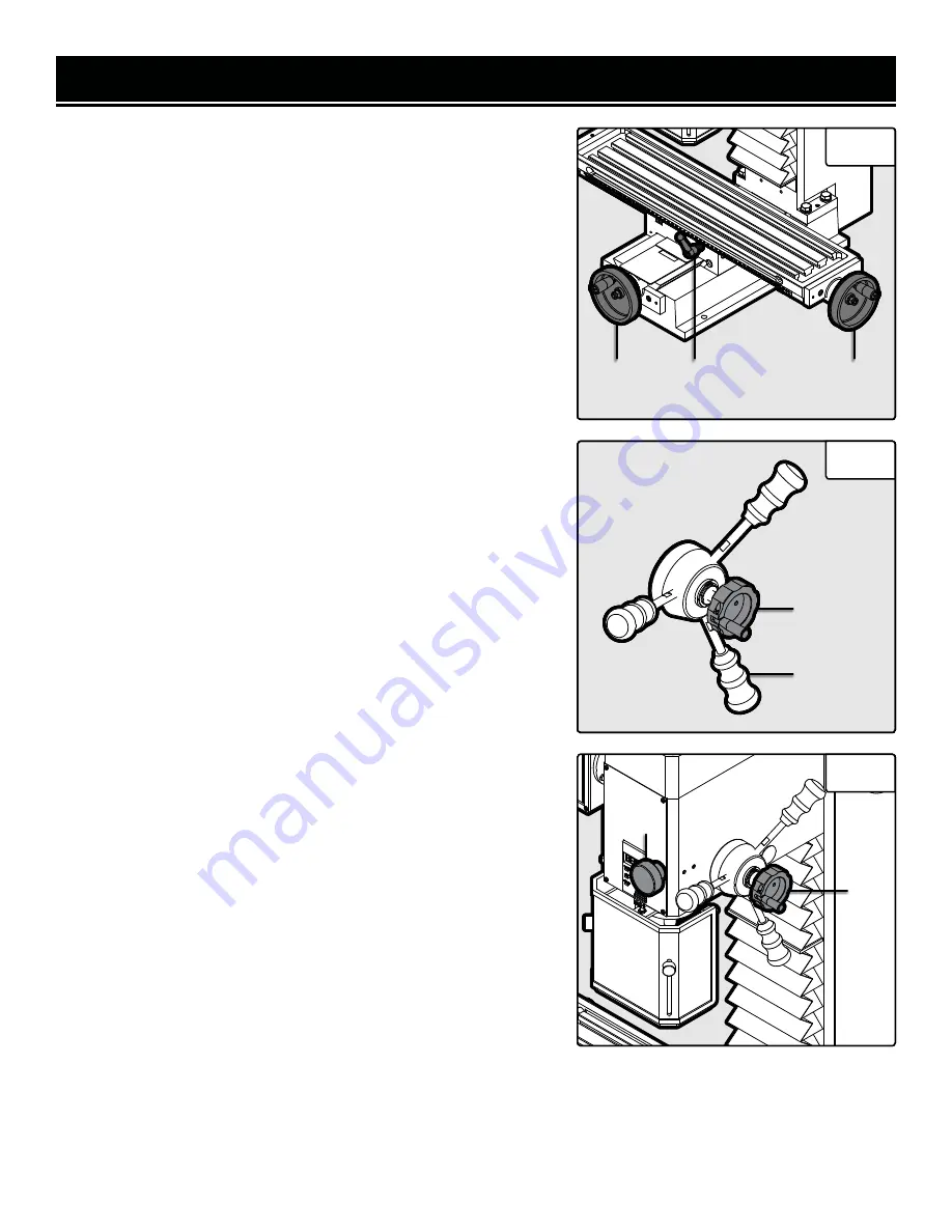
The milling machine’s worktable can be adjusted along the X axis and
Y axis to accurately control the cutting location. The gauge on each
handwheel indicates the distance of travel.
1. To move the table along the longitudinal (X) axis (left and right),
loosen the longitudinal feed lock lever (Fig. 6 - 1), engage the cross
axis handwheel (Fig. 6 - 2) with the clutch teeth and rotate the longi-
tudinal handwheel. Tighten the longitudinal feed lock lever to lock the
longitudinal travel.
2. To move the table forward and back along the cross (Y) axis, loos-
en the cross feed lock lever, and rotate the cross feed handwheel (Fig.
6 - 3). Tighten the cross feed lock lever to lock the cross travel.
NOTE:
The lock lever can be pulled outwards and repositioned on the
screw if the handle cannot be completely rotated due to interference
with another part.
ADJUSTING THE SPINDLE DEPTH
For normal feeding, the downfeed selector knob
(Fig. 7 - 1)
should be
lose and disengaged. Rotate the downfeed feed handles (Fig. 7 - 2) to
bring the headstock up or down. Use the digital depth readout in the
front of the machine to read the cutting depth.
For fine feeding adjustment
(down to 0.001 inch increment)
, rotate
the downfeed selector knob clockwise (Fig. 8 - 1) until it is tight. Then
rotate the fine downfeed knob (Fig. 8 - 2) to make fine adjustments to
the headstock position. Use the digital depth readout in the front of
the machine to read the cutting depth.
NOTE:
The spindle is equipped with a depth lock. To engage the depth
lock, insert the 8 mm hex wrench in the depth lock and rotate clock-
wise until it is tight and engaged. To disengage the spindle depth
lock, insert the 8 mm hex wrench and rotate the spindle depth lock
counter-clockwise until it is loose and the spindle can move smoothly
with the normal or fine downfeed handles. Be aware not to try to
adjust the spindle depth while the spindle depth lock is engaged as
doing so might cause extreme damage to the spindle.
Fig. 6
1
2
3
Fig. 7
Fig. 8
1
2
1
2


