


86
WELGER RP 202 • RP 220 • RP 302 • RP 320
13.
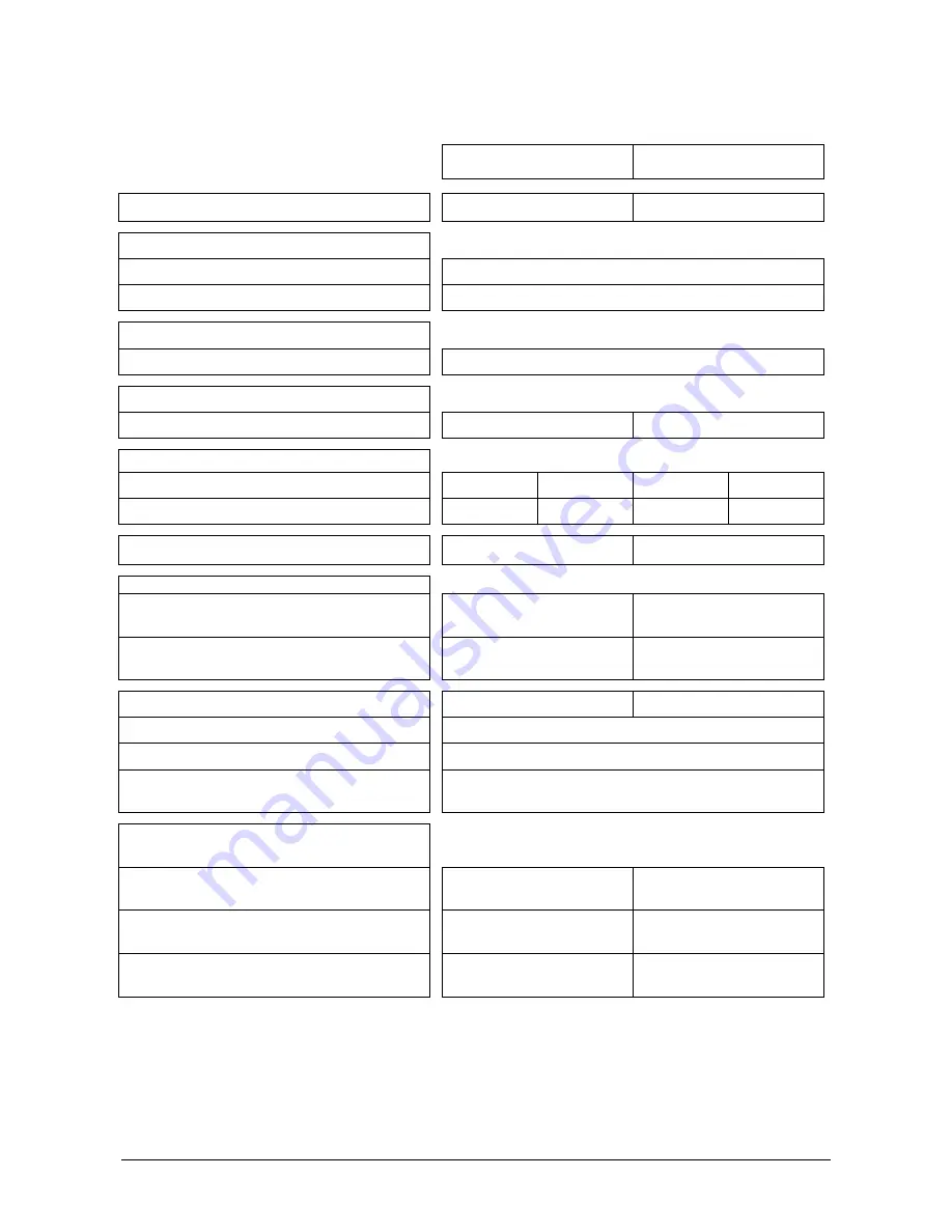
Technical Data
RP 202
RP 220
Roll chamber (
∅
x width) [m]
approx. 1.25 x 1.23
approx. 1.25 x 1.23
Twine wrapping* with
a) Hemp twine
Running length: 200 or 330 m/kg
b) Plastic twine
Running length: 400 to 750 m/kg
Net wrapping* with
Quality roll bale net
Length: 2000 or 3000 m / width: max: 1.30 m
Binding material supply
Twine / Net
4 rolls / 2 rolls
1)
4 rolls / 2 rolls
1)
Pick up unit
Pick up unit width [m]
1.50 2.00 2.00 2.25
Rake width [m] DIN 11220
1.35 1.80 1.80 2.06
Rpm of tractor pto shaft [min-
1
]
540 540
Required outlets
Lighting outlet
12 V (7-pin plug)
Wrapping control outlet (BALERCONTROL)
12 V DIN 9680 A
Max. length [m]
4.21
4.50
Width, without pick-up unit support wheels [m]
2.30 – 2.56
Height [m]
2.44 – 2.54
Shipping weight, with binding materials at
least [kg]
see data plate on the baler
Model-dependent permissible maximum
speed limit
CLASSIC, SPECIAL
25 km/h
2)
–
FARMER, MASTER, PROFI, without brakes
–
25 km/h
2)
FARMER, MASTER, PROFI,
with air brakes
–
40 km/h
2)