background image

7

2.20 

Operation and System Optimization

2.21 

High Pressure Operation


DUOSEAL two-stage pumps are designed to be most efficient when operated at or near their ultimate blanked off 


pressure.  The pump is designed to remove air from a vacuum system at atmospheric pressure to a deep vacuum. 


When the pump is operated at elevated pressures up to about 10 Torr for long periods of time, the pump will run 


hotter.  At elevated ambient temperatures under these conditions, the thermal protection switch on single phase 


motors may cut out.  Use of an exhaust filter with coalescing element is required.


Leaky vacuum systems, too large a vacuum chamber for pump size or high gas loads to the vacuum systems 


are causes for extended runs of the pump at elevated pressure.  If you need additional information, please contact 


Welch Vacuum at 847-676-8800, extension 1, for further information and precautions.

2.22 

Principle of Gas Ballast

2.221  Effects of Unwanted Vapor


Systems which contain undesirable vapors cause difficulty both from the standpoint of attaining desirable ultimate


pressures as well as contamination of the lubricating medium.  A vapor is defined as the gaseous form of any 


substance which is usually a liquid or a solid.  Water, oil and a mercury vapors are three of the more common 


vapors encountered in typical vacuum systems.  When such vapors exist in a system, the vapors or mixtures of 


gas and vapor are subject to condensation within the pump; the precipitated liquid may thus ultimately dissolve 


or become emulsified with the lubricating medium.  This emulsion is recirculated to the chambers of the pump 


where it is again volatilized causing increased pressure within the system.

2.222  Presence and Removal of Condensate


Condensation takes place particularly in the compression stroke of the backing or second stage of a two-stage 


pump.  The compression stroke is that portion of the cycle during which the gas drawn from the intake port is 


compresses to the pressure necessary to expel it past the exhaust valve.  Condensation takes place when the ratio 


between the initial pressure and the end pressure of the compression is high, that is, when the mixture of vapor 


and gas drawn from the intake port is compressed from a low pressure to high pressure.  By adding air though the


gas ballast valve to the mixture of vapor and gas being compressed, the pressure required for delivery past the 


exhaust valve is reached with a considerably smaller reduction of the volume of the mixture; this, depending upon 


the amount of air added, condensation of the vapor is wither entirely avoided or substantial reduced.

2.223  Pump Function With Gas Ballast


In a pump functioning on a contaminated system and operating without the gas ballast, compression within the 


stage takes place in the normal manner until the saturation pressure of the contaminating vapor contained within


the mixture of gas and vapor is reached.  The saturation pressure of water vapor is that pressure and corresponding 


temperature at which the dew point of the vapor is reached and condensation occurs.  The saturation pressure of 


water vapor at an ambient temperature of 20°C is 17.5 Torr, while at 60°C, the approximate operating temperature


of a pump, the saturation pressure is 149 Torr.  The external side of the exhaust valve is subjected to atmospheric 


pressure.  Consequently a compressive force somewhat greater than atmospheric pressure is required to open the 


valve and permit expulsion of the gas.  Sometime during increased compression of the mixture of gas and vapors, 


the saturation pressure of 149 Torr for the water vapor is reached and the vapor condenses.  The condensate is 


then allowed to emulsify with the oil which is recirculated within the pump stages this providing continued 


contamination of the system.

2.224  Pump Function With Gas Ballast


On the other hand, when ballast air at atmospheric pressure is supplied to the compression stroke by means of the


gas ballast, the partial pressure of the unwanted vapor becomes a very small part of the total pressure of the 


mixture of gas, vapor and newly supplied air.  The vapor is thus prevented from reaching its saturation pressure 


corresponding to the temperature of the pump and is finally expelled form the pump as a vapor.

2.225  Controlled Ballast Flow


Some degree of variation in ballast flow may be obtained by the amount of opening applied tot he gas ballast.  


Two or more turns of the gas ballast are sufficient to open it wide.  With the gas ballast open, the sound of the 


exhaust is similar to that of a pump operating against a large leak.  Because of the increased pressure introduced 


into the compression stroke, the pump must work a little hard to function, thus resulting in an increased 


operating temperature of approximately 8°C over a prolonged period of time.  Tests have shown that continuous 


and prolonged operation for several weeks under these conditions is not injurious to the pump.

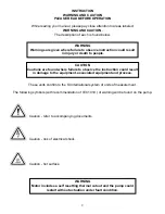
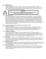
CAUTION

Do not run this pump for prolonged periods of time at or above

10 Torr.  The  pump will overheat, excessive oil mist will be 

emitted from the exhaust and the pump will eventually seize.

Summary of Contents for DUOSEAL 1399B-01

Page 1: ...sting and causing possible injury to personnel in the area Gardner Denver Thomas Inc Welch Vacuum Technology 5621 W Howard Street Niles IL 60714 Phone 847 676 8800 Fax 847 677 8606 Technical Support 847 588 2366 E Mail gdwelchvacuum gardnerdenver com Part No 67 2063 Web Page www welchvacuum com Printed in USA SAVE THESE INSTRUCTIONS Manufactured in an ISO 9000 Registered Environment 505 872 0037 i...

Page 2: ...ions are found where failure to observe the instruction could result in damage to the equipment associated equipment and process These units confirm to the SI International system of units of measurement The following symbols with recommendation of IEC1010 of warning will be found on the pump Caution refer to accompanying documents Caution risk of electrical shock Caution hot surface WARNING Motor...

Page 3: ...evel 10 3 30 Shaft Seal Replacement 10 3 40 Repairing Oil Leaks 11 3 50 Repairing Vacuum Leaks 11 3 60 Drive Problems 11 Section 04 Trouble Shooting Guide 4 10 Poor Vacuum Readings 12 4 20 Noisy Pump 12 4 30 Excessive Oil Mist 12 Section 05 Quick Reference Chart Chart 1 13 Chart 2 13 Section 06 Dimenional Drawings with rotation Vacuum Pump 14 Section 07 Pumping Speed Curves Speed Curves 15 Section...

Page 4: ...y to drive your particular pump at the recommended speed 1 13 Pump Location The pump should be located preferably in a clean and well ventilated area and adequate space should be provided wherever possible for routine maintenance such as changes of oil and belt adjustments and replacements Above all the pump should be located as closely as possible to its system in order to utilize it most efficie...

Page 5: ...he gas flow is substantially molecular in character The gas flow is then dependent upon the kinetic activity of the molecules to bring it to the intake of the pump 1 162 The Effects of Conductance It has been shown that the conductance of a tube is proportional to the cube of its radius and inversely proportional to its length Therefore it is imperative that the connecting lines be as large in dia...

Page 6: ...ze yourself with the function and action of the pump which you have now required Remove the intake and exhaust port plugs and temporarily provide a stopper for the intake and a dust cap for the exhaustReview the power requirements as described in Section 1 4 2 103 Cleanliness Take every precaution to prevent foreign from entering the pump A fine mesh screen is provided for this purpose in the inta...

Page 7: ...of the volume of the mixture this depending upon the amount of air added condensation of the vapor is wither entirely avoided or substantial reduced 2 223 Pump Function With Gas Ballast In a pump functioning on a contaminated system and operating without the gas ballast compression within the stage takes place in the normal manner until the saturation pressure of the contaminating vapor contained ...

Page 8: ...s rich in hydrogen and observing a sudden change in pressure on an electrical gauge The difference in calibration of these gauges for air and other gases will produce a distinct change in the pressure reading To use this method of detection the system must be under vacuum and the gauge sensing tube must be located between the pump and the area to be probed Use extreme caution as these materials ar...

Page 9: ... system The required frequency of changes will vary with the particular system Experiences with the process will help you determine the normal period of operation before an oil change is required 3 103 Oil Overheating This pump is designed to operate continuously below 10 Torr Continuous operation of this pump above 10 Torr will lead to overheating and eventual pump failure See Section 2 21 High P...

Page 10: ... rubber stopper Turn the pump on and run the pump for 10 minutes Close the gas ballast 8 Check the vacuum reading of the pump by connecting a thermocouple gauge tube to the pump s intake If the pump is running nearly as good as when it was new the total pressure reading you will read on wither of these two gauges will be at least 10 micron A simple way to connect the gauge tube to the pump is to r...

Page 11: ...ing surfaces cleaned of any nicks 3 50 Repairing Vacuum Leaks 3 501 Surface Preparation Good Vacuum seals are an essential and important attribute of a good mechanical pump A good seal is dependent upon the quality of the mating surfaces as well as the sealant and its preparation The mating faces should be carefully inspected for any projections or foreign particles which might interfere with prop...

Page 12: ...ut a forced oil flush 5 If noise level is still unsatisfactory consult with WELCH Technical Service at 847 676 8800 Ext 1 4 30 Excessive Oil Mist 1 Check oil level Maintain the level between the two lines on the oil window during operation Too high a level will cause excess oil mist 2 Determine the vacuum level in your system with a thermocouple gauge or manometer Be sure the pump is operating at ...

Page 13: ...02 Wired for 230V 60Hz 3Ph N A Wired for 230V 50Hz 3Ph N A Replacement Parts Shaft Seal Lip Seal 1401E 01 Shaft Seal Mechanical Seal 1401D Air Filter Screen 41 0660 Intake Chamber Cover Gasket 41 0234 Oil Case Gasket 41 0403 Drain Plug 61 2278 Oil Window 41 3753 Large Vane 41 0959 Small Vane N A Large Vane Spring 41 1304 Small Vane Spring N A Large Vane Spring Holder 41 1685 Repair Kits Minor Repa...

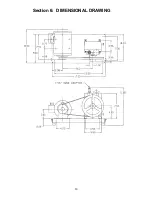
Page 14: ...14 Section 6 DIMENSIONAL DRAWING ...

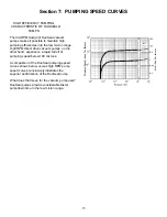
Page 15: ...range High RPM direct drive vacuum pumps on the other hand experience a rapid fall off of pumping speed below 100 microns A comparison of the DuoSeal pumping speed curves shown below versus high RPM pump speed curves conclusively illustrates the superior performance of the DuoSeal pump What does that mean for the vacuum pump user DuoSeal pumps provide considerable faster pumpdown time in the low m...

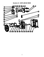
Page 16: ...16 Section 8 EXPLODED VIEW ...

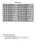
Page 17: ...or Repair Kit Catalog 1399K 03 Item 33 exploded view shown on page 18 1401E is a Mechanical Seal Kit which fits all model 1399 serial numbers There is a lipseal on pumps beginning with serial number 25773 and higher It is available as a kit part number 1401E 01 ITEM QTY P N A B DESCRIPTION 20 1 41 1239 1 1 EXHAUST VALVE 21 1 41 1285 1 1 STEEL WASHER FOR SHAFT COLLAR 22 2 41 1304 2 2 VANE SPRING 23...

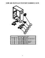
Page 18: ...ST FOR PART NUMBER 41 2378 Parts List for Model 41 2378 Item Qty P N Description 1 4 2 01 0308 Screw Hex Hd 5 46 18x1 2 2 2 41 1049 Pump Leg 3 1 41 2088 Oil Case Machined 4 1 41 3753 Oil Case Window 5 1 61 2278 Drain Valve ...

Page 19: ...on kit Cat No 141601 for models1400 1405 1376 1380 1402 Standard Exhaust Filter Use with pump model Dimension Catalog Number Diameter Height Filter Replacement Element 1392 1399 1400 1376 1380 1402 1400 1397 1374 2 5 5 5 2 5 6 25 9 1417 1417P 10 1417P 20 1417L 1417G 1417H 01 Directional Exhaust Filter Use with pump model Dimension Catalog Number Diameter Height Outlet Tube O D Filter Replacement E...

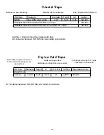
Page 20: ...r Height A2 Cat No 1 NW16 to 4 CFM 140 L min 3 75 5 25 8 25 541001 Stainless Steel Element for ISO NW 16 Trap 1 541921 Stainless Steel Element for ISO NW 25 and NW 40 Traps1 541922 Removable 3 quarter center well for dry ice alcohol slurry do not use acetone Visible trapping surface Cold temperature up to 12 hours depending on vapor load Available with straight tube connections ISO Size Diameter H...

Page 21: ...uum Technology and receipt or possession does not convey any rights to loan sell or otherwise disclose said information reproduction or use of said information for any purpose other than that in connection with said information was supplied may not be made without express written permission of Welch This document is to be returned to Welch upon request and in all events upon completion of the purp...

Reviews: