background image

4–8

Programming the Scanner

Append Buffer

This wand Selection controls the status of the Append Buffer.  When
enabled, the Append Buffer stores messages (for example from a
“barboard”), until a) it overflows, or b) a symbol without Append or in a
new symbology is scanned.  When either of these events occur, the
contents of the buffer are transmitted, followed by the most recent scan.
The Append Buffer must be enabled (“Yes”), whenever the decoder is
configured to read Code 93, Code 128 or Code 3 of 9 symbology with
Append Option.

RTS/CTS Protocol

Note:

This feature is not supported in all wand models/software revisions.

This selection enabled will require RTS/CTS Protocol for communications.
Connector Option 3 or 4  must be selected to support this programming
feature.  Refer to page 2–7 or Appendix B.3 for information on Option 3 or
4.

4.4 SYMBOLOGY SELECTION Menu Page

This Menu Page is used to program decoding selections.  The wand can be
configured to recognize and decode up to nine (9) popular bar code
symbologies by scanning the proper code enabling (Selection) symbols on
this Programming Menu page.  After a particular code has been enabled,
scanning the associated (Variable) code(s) will further program that
symbology’s decoding parameters.

Keep in mind that at power–up (or upon reset), the wand will automatically
configure operating parameters to the last programmed values.  Code
options which are enabled (“Yes”) will become the active operating
parameters unless they are changed by the proper configuration command.
Code options with an asterisk (*) next to the (“No”) will automatically be
disabled unless they are changed by the proper configuration command.

Note:

To obtain maximum security when scanning bar codes, it is
recommended that only those symbologies actually being used be
enabled.  Symbologies not being used should be disabled.  Additional
data security can be achieved by programming the maximum and
minimum character counts when they are known.

Summary of Contents for Scanteam 6180

Page 1: ...Serial Interface RS 232 Decoded Out Wand Technical Manual ...

Page 2: ......

Page 3: ... to try to correct the interference by one or more of the following measures FCC Class B Compliance Statement Caution Any changes or modifications made to this device that are not expressly approved by Welch Allyn Inc may void the user s authority to operate the equipment Note To maintain compliance with FCC Rules and Regulations cables connected to this device must be shielded cables in which the...

Page 4: ... in specifications and other information contained in this document without prior notice and the reader should in all cases consult Welch Allyn to determine whether any such changes have been made The information in this publication does not represent a commitment on the part of Welch Allyn Welch Allyn shall not be liable for technical or editorial errors or omissions contained herein nor for inci...

Page 5: ...scharges and electricity the responsibility to protect it from static damage is solely that of the user The warranty is valid only if the wand has not been tampered with or serviced by any party unauthorized by Welch Allyn Inc as a repair facility THE WARRANTIES SET FORTH HEREIN ARE IN LIEU OF ANY AND ALL OTHER WARRANTIES EXPRESSED OR IMPLIED INCLUDING THE WARRANTIES OF MERCHANTABILITY AND FITNESS...

Page 6: ...Limited Warranty ...

Page 7: ...s 2 1 2 2 Main Elements of the 6180 System 2 1 2 3 Operating Theory 2 2 2 4 Factors Affecting Scanner Performance 2 2 2 4 1 Scanner Illumination Source 2 2 2 4 2 Scanning Aperture 2 2 2 4 3 Depth of Field 2 3 2 4 4 Scanning Velocity 2 4 2 4 5 High Low Density Bar Codes 2 4 2 4 6 Print Contrast 2 4 2 5 Interface Description 2 5 2 7 External Power 2 8 Chapter 3 Setup and Installation Section Page 3 ...

Page 8: ...n Example 4 10 4 7 Configuring the 6180 Using WANDMENU 4 13 4 7 1 Installing WANDMENU 4 15 4 7 2 WANDMENU Control Options 4 16 4 7 3 Programming Control 4 17 4 7 4 Making Menu Selections 4 18 Chapter 5 Maintenance and Troubleshooting Section Page 5 1 Scanner Maintenance and Service 5 1 5 2 Cleaning 5 1 5 3 Inspection 5 2 5 4 Troubleshooting 5 2 5 5 Obtaining Factory Service in the U S 5 3 5 6 Obta...

Page 9: ...ronmental Specifications A 7 A 5 Mechanical Specifications A 7 A 6 Bar Code Symbol Specifications A 9 Index List of Illustrations Figure Page Figure 1 1 SCANTEAM 6180 with External Power Plug 1 1 Figure 2 1 Aperture and Depth of Field 2 3 Figure 2 2 Range of Angle 2 4 Figure 2 3 SCANTEAM 6180 Input and Output Circuits2 7 Figure 2 4 SCANTEAM 6180 Input and Output Circuit for the True RS 232 Scanner...

Page 10: ...scription of the operating system explaining how the scanner works and how it reads decodes a bar code symbol Scanner identification and scanning techniques are discussed Chapter 3 explains how to set up and install your scanner Instructions to confirm scanner operation and to check bar code labels is provided Chapter 4 explains how to program your scanner to meet your specific needs Refer to Chap...

Page 11: ...s Roger C Palmer 1989 Helmers Publishing Inc 174 Concord Street Peterborough NH 03458 603 924 9631 Handbook of Bar Coding Systems Harry E Burke 1984 NCR Corporation Van Nostrand Reinhold Company Inc 115 Fifth Avenue New York New York 10003 Automatic ID Resource Catalog AIM USA Publications 634 Alpha Drive Pittsburgh PA 15238 2802 Fax 412 963 8753 Phone 412 963 8588 AIM Guidelines on Symbology Iden...

Page 12: ...vi Table of Contents ...

Page 13: ...d illumination and a stainless steel housing The SCANTEAM 6180 reads and decodes nine 9 popular bar code symbologies and outputs the bar code data to any host having an RS 232 port using asynchronous serial ASCII format 1 2 Hardware Description The standard SCANTEAM 6180 unit consists of the wand body a 6 1 8m coil extended or straight interface cord and the 9 pin D metallized plastic shell termin...

Page 14: ... menu which is supplied with the unit The wand may also be programmed through a host download method which utilizes a PC based menu program Software and instructions for implementing this optional programming technique are described in Section 4 6 of this manual The 6180 may be programmed to autodiscriminate among the following bar code symbologies and their variations Codabar Code 3 of 9 UPC EAN ...

Page 15: ... Bar Code System The major operational elements of the SCANTEAM 6180 include the scanner optics the digitizing electronics and the decoding circuitry The key components of the scanner optical system are the illumination source LED and the illumination sensor photodiode Both the LED and photodiode are positioned directly behind a specially designed lens in the scanner body Cable connections are mad...

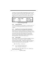
Page 16: ...e symbol 2 4 Factors Affecting Scanning Performance The following factors influence reading performance and should be considered when selecting a contact scanner for a particular bar code application 2 4 1 Scanner Illumination Source Wand type scanners are equipped with a visible red 660nm source Red illumination is compatible with most printing inks including most thermal papers Because it provid...

Page 17: ...ommended that the aperture dimension be no less than 0 7 times the X width of the narrowest bar code coding element dimension to be read An aperture size that is slightly smaller than the narrowest bar code element 0 9 times X provides optimum resolution of the bars and results in the generation of a digital signal which accurately represents the bar code An 8 mil 0 2mm aperture is often a good co...

Page 18: ...lly given in terms of the X dimension the width of the narrowest bar code element As bar code density increases the width of the narrowest bar code element decreases The scanning aperture should always be smaller then the narrowest element to assure optimum resolution and the generation of a digital signal which accurately represents the bar code 2 4 6 Print Contrast Print contrast is a measure of...

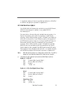
Page 19: ...interface cable will be terminated in a 9 pin D female connector Power will be available on pin 9 If Option 4 is specified RTS CTS lines are used and the cable will be terminated in a 9 pin D female connector with a pigtailed 5 pin DIN female connector for power Pin assignments for each option are shown below A complete wire color code function description of the interface is provided in Appendix ...

Page 20: ... Pin 6 CTS Pin 7 RTS Pigtail Power Plug Pin 1 Ground Pin 3 5VDC 5 This feature is not supported in all wand models software revisions Connector pin 2 is reserved for data transmitted from the wand to the host It obeys RS 232 data formats but uses 0 to 5V logic swings It is in effect TTL RS 232C logic It is also available in true RS 232 levels Connector pin 3 is reserved for data sent to the wand T...

Page 21: ...Circuits Schematic diagrams of the input and output circuits for the true RS 232 levels are shown in Figure 2 2 The operation of the DS1275 chip is unique in that it steals current from the receive input when transmitting a negative swing Since most serial communications ports remain in a negative state statically using the receive signal for negative power greatly reduces current consumption DS12...

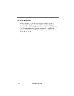
Page 22: ... when it cannot be supplied by the host and the 9 pin D connector with pigtail power plug is ordered A 5VDC transformer type power supply both with 5 Pin DIN male connectors that directly interface with the pigtail power plug may be ordered The 5VDC power supply can be ordered to operate at 110VAC or 220VAC ...

Page 23: ...o delivered the shipment Damage claims due to handling during shipment should be placed directly with the carrier When all components have been identified and checked prepare the wand for service using the following procedure 3 3 Set up And Installation 1 Position the host unit power switch to the OFF position 2 Attach wand to host device If external power will be supplied by the host device inser...

Page 24: ...plied to an item can cause a reading problem This completes installation of the wand to the host system The wand reader decoder must now be configured to the particular decoding application Welch Allyn offers two programming methods The standard programming technique involves using the wand to scan bar code symbols from a Programming Menu An alternative programming method makes use of an optional ...

Page 25: ...mit the user to select and download decoder parameters from the host The configuration program WANDMENU is driven by a PC Operating parameters are selected using a menu displayed on the PC screen WANDMENU software allows the user to simultaneously display the current status of all decoder parameters and to save a desired decoder configuration for use at a later time 4 2 The Programming Menu The co...

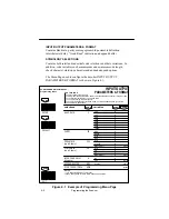
Page 26: ... BAUD RATE 150 300 600 scan scan scan scan scan 1200 2400 4800 9600 A B C D E F NOTES 1 Designates DEFAULT selections PARITY Mark Space Even Odd A B C D PREAMBLE up to 5 chars G 19200 H To add preambles postambles and or code identification character to the bar code To set intercharacter delay to a specific value POSTAMBLE To control scanning indicator blink up to 5 chars APPEND BUFFER Yes No STX ...

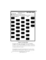
Page 27: ... the Bar Code Chart i e Roman Numeral Letter or Number that the user must scan in order to configure a particular decoder parameter to a desired value ENTER At the top of each Menu Page is a symbol labeled ENTER which is unique to that Menu Page The ENTER command activates that Menu Page and must be scanned before configuring parameters shown on that page 4 2 2 The Bar Code Chart The SCANTEAM 6180...

Page 28: ...F 0 YES 1 NO 2 3 4 5 ESCAPE DEFAULT W A ROMAN NUMERALS LETTERS DIGITS OTHERS SCANTEAM SRD 6180 SID 6280 Programming Menu Figure 4 2 Bar Code Chart Note that the chart contains symbol groupings that include ROMAN NUMERALS LETTERS and NUMBERS The sequence in which these symbols are scanned generates the programming instructions which enable or disable specific decoder functions The right hand column...

Page 29: ...ed above the WA symbol generates a global command It is intended to be used in conjunction with the DEFAULT symbol to reset all wand decoder parameters to their default values The sequence scan WA followed by scan DEFAULT will cause all Selections and Variables on both menu pages to reset to their default values EXIT Scanning the EXIT symbol produces a command which can be used to terminate progra...

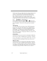
Page 30: ...k Space Even or Odd parity options Preamble Preambles are assigned using the programming menu When the Preamble selection is enabled any combination of up to five identifiers are transmitted as a header immediately preceding scanned bar code data Preamble characters may include Start Transmission STX Code ID and the ASCII characters 00 7F These characters will be transmitted in the order in which ...

Page 31: ...e bar code messages Up to five 5 postambles including End Transmission ETX Carriage Return CR Line Feed LF and the ASCII characters 00 7F can be programmed Postamble characters will be transmitted in the order in which they are selected Since postamble selections also begin with a clean slate the programming sequence SCAN ENTER SCAN IV SCAN EXIT will remove existing postambles from the decoder con...

Page 32: ...Page is used to program decoding selections The wand can be configured to recognize and decode up to nine 9 popular bar code symbologies by scanning the proper code enabling Selection symbols on this Programming Menu page After a particular code has been enabled scanning the associated Variable code s will further program that symbology s decoding parameters Keep in mind that at power up or upon r...

Page 33: ...ermitted in the bar code message 4 5 Message Format The wand will transmit data automatically to the host as soon as a bar code symbol is scanned Each data transmission consists of three main elements 1 a PREAMBLE 2 the MESSAGE consisting of the bar code data and 3 a POSTAMBLE The actual content of the data transmission will depend upon the Preamble and Postamble characters and the decoded bar cod...

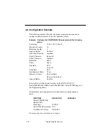
Page 34: ...haracter Required Check Character Transmit Baud Rate 4800 Parity Space Preamble STX Code ID Postamble ETX Intercharacter Delay 25 ms Indicator Control Beep on Reset Beep on Good Read Append Buffer Enabled Refer to the Selections Variables table on the INPUT OUTPUT PARAMETERS FORMAT and SYMBOLOGY SELECTIONS pages of the Programming Menu Program these operating parameters following the scanning sequ...

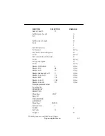
Page 35: ...o Yes 0 Yes Set Append Option G To Yes 0 Yes Disable CODABAR I 1 No Disable UPC III 1 No Disable EAN IV 1 No Disable Interleaved 2 of 5 V 1 No Disable Code 2 of 5 VI 1 No Disable MSI VII 1 No Disable Code 93 VIII 1 No Disable Code 128 IX 1 No Store programmed values by exiting the SYMBOLOGY SELECTION Menu Page EXIT Enter I O PARAMETERS FORMAT Menu Page ENTER Set Baud Rate I To 4800 F Set Parity II...

Page 36: ...T Note In the previous example all desired operating parameters were scanned to illustrate the scanning process In actual practice it would not be necessary to program those parameters which default to desired values i e Append Buffer Code ID Transmit Start Stop Characters etc In addition in order to maximize reading accuracy all of the unused codes were disabled When this protection is desired it...

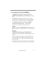
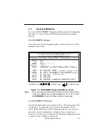
Page 37: ...ns of the Configuration Disk files are given below READ ME Entering the command C A TYPE READ ME from the DOS prompt will generate a display which explains the general use of each EXE file on the disk WANDMENU This program allows you to accept read save and install desired configurations for the SCANTEAM 6180 Configuration data is transferred to the scanner through the PC s serial communication ch...

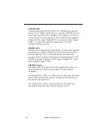
Page 38: ...capability from the scanner When the UNINSTAL EXE routine has been run the SCANTEAM 6180 will revert to normal operation and transmit any scanned label data according to the designated symbology format s The UNINSTAL program is transferred to the scanner through the PC s serial communication channel COM1 XON XOFF Feature The SCANTEAM 6180 has an XON XOFF capability that allows you to control data ...

Page 39: ...REQ D ON Length 01 64 ON Length 04 48 ON Length 00 60 ON All Modes Length 00 80 Leading FNC1 NOT_REQ D ON Length 01 48 2 Check Digits OFF Xmit Check Char OFF OPERATION Use to MOVE Cursor to CHANGE Entry BaudRate Parity Preamble Postamble InterChrDelay Indicators Features Codabar Code 39 UPC Code EAN Code Intr 2 5 Reg 2 5 MSI Code Code 93 Code 128 Code 11 Figure 4 3 WANDMENU Programming Menu Screen...

Page 40: ... LOAD Setting mode is highlighted and the ENTER key is first depressed the user will be prompted for a file name FILENAME To continue the user should enter the file name or depress the ENTER key LOADing the file named DEFAULT causes default settings to be loaded Attempting to LOAD a non existent file will result in an error message SAVE_Settings This mode allows the user to save store a certain de...

Page 41: ...etting except in a few special cases which will be explained later in this section The active menu element the control option and the specific decoder parameter is indicated by the position of the cursor A decoder operating parameter selection and variable must be highlighted before it can be changed Arrow Keys In addition to moving the cursor around the menu to the desired position in certain pos...

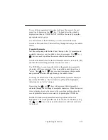
Page 42: ...ll cause those values to be stored The key can then be used advance the cursor to the next menu selection Postamble 4 7 4 Making Menu Selections The following sections explains the functions of the ENTER and the four arrow keys as they relate to specific menu selections Start Up At start up the cursor will automatically default to the LOAD Settings control option and it will be highlighted Depress...

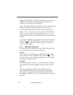
Page 43: ...elections are vacant The ENTER key is used to specify which of the preamble or postamble characters will be programmed Once a preamble postamble position is active the and keys are used to increment that preamble and postamble selection through the range of available values To change the default value or to program additional preamble characters depress the ENTER key The first character ID will be...

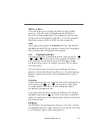
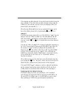
Page 44: ... selection to toggle to Wake Up Blink OFF the disabled state Depressing the key will move the cursor to the Good Read Blink selection This selection can also be toggled ON or OFF using the ENTER key Remember that the Blink Scanner selection must also be ON enabled whenever the Wake Up or Good Read indicator functions are desired When Indicator selections have been made leave the Indicator menu lin...

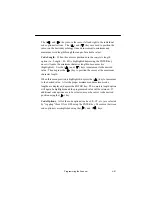
Page 45: ...d Use the and keys to increment to the desired value Then depress the key to position the cursor at the maximum character length When this menu position is highlighted depress the key to increment to the desired value After the proper minimum and maximum code lengths are displayed depress the ENTER key The complete length option will again be highlighted and the programmed value will be retained I...

Page 46: ...4 22 Programming the Scanner ...

Page 47: ...antly to dependable scanner operation The sapphire tip is designed to be maintenance free but may be cleaned when necessary The tip of the scanner must be kept clean to assure high first pass reading performance Since a dirty tip can impair scanning performance the tip should be examined whenever scanning performance begins to degrade or if the tip has become visibly dirty If the tip becomes dirty...

Page 48: ...e it is properly attached to the host P C 2 Confirm that the decoder is properly configured for the bar code symbology 3 Inspect the quality of the bar code symbols that are being used Symbols that are of a low contrast scratched or otherwise defaced may cause scanning problems To verify scanner operation test the system with a high quality bar code symbol As an additional check verify the quality...

Page 49: ...ming these checks factory service may be required 5 5 Obtaining Factory Service in the United States Welch Allyn provides service for all its products through a service center located at its manufacturing facilities in Skaneateles New York To obtain warranty or non warranty service return the unit to Welch Allyn postage paid with a copy of the dated purchase record attached Please contact the Welc...

Page 50: ...hone Int 353 1295 0750 Fax Int 353 1295 6353 U K Office Dallam Court Dallam Lane Warrington Cheshire WA2 7LT England Telephone Int 44 1925 240055 Fax Int 44 1925 631280 5 7 Obtaining Factory Service in Asia For service in Asia please contact your Welch Allyn representative at address below or your local distributor Welch Allyn Hong Kong Office 10 F Tung Sun Commercial Centre 194 200 Lockhart Road ...

Page 51: ...r please call your Distributor or the nearest Welch Allyn technical support office North America Telephone 315 685 2476 8am to 6pm EST Fax 315 685 4960 E Mail dcd_techsupt mail welchallyn com Europe United Kingdom Telephone Int 44 1925 240055 Ireland Telephone Int 353 1216 0070 Asia Telephone Int 852 2511 3050 or 2511 3132 ...

Page 52: ...5 6 Maintenance and Troubleshooting ...

Page 53: ... inch 0 05mm A 2 Optical Specifications Effective Scanning Aperture 6 10 mil Light Source Red LED Wavelength 660 nm Depth of Field Aperture Depth of Field X Dimension Tilt Angle Aperture Range of Angle X Dimension A 3 Electrical Specifications The scanner will function but may not operate within the specified tolerances if the operating voltages indicated below are exceeded Operating Voltage 4 5 V...

Page 54: ...mit Data 3 Black RX Receive Data 4 Not Used 5 White GRND 6 Not Used 7 Not Used 8 Not Used Ground 9 Power to Scanner Shell Drain Shield EMI RFI Braid Pin Assignments Red 5VDC Shield Isolation The resistance between the shield and the power supply common termination exceeds 1 meg ohm The flashover voltage exceeds 40VDC A 10KHz AC signal with an amplitude of 1 0 pp can be placed between the shield an...

Page 55: ...Size Type RS 232 Port 9 pin female type D Metal shell with 5 pin DIN female Pigtail 5 3 2 3 1 To Scanner Pin Color Code Signal 1 Function 2 3 Red 5VDC Power to Scanner 4 Not Used 5 GRND Ground Not Used Shell Drain Shield Braid 5 Pin DIN Connector Pin Assignments White Not Used 9 Pin D Connector Pin Assignments on next page ...

Page 56: ...RND 6 Not Used 7 Not Used 8 Not Used Ground 9 Not Used 9 Pin D Connector Shell Drain Shield EMI RFI Braid Pin Assignments Shield Isolation The resistance between the shield and the power supply common termination exceeds 1 meg ohm The flashover voltage exceeds 40VDC A 10KHz AC signal with an amplitude of 1 0 pp can be placed between the shield and the common termination with no operational affect ...

Page 57: ... Data 3 Black RX Receive Data 4 Not Used 5 White GRND 6 Not Used 7 Not Used 8 Not Used Ground 9 Not Used 9 Pin D Connector Shell Drain Shield EMI RFI Braid Pin Inner 5VDC Outer Ground Function Barrel Connector Pin Assignments Shield Isolation The resistance between the shield and the power supply common termination exceeds 1 meg ohm The flashover voltage exceeds 40VDC A 10KHz AC signal with an amp...

Page 58: ...ck RX Receive Data 4 Not Used 5 White GRND 6 Not Used 7 Clear to Send 8 Request to Send Ground 9 Power to Scanner Shell Drain Shield EMI RFI Braid Pin Assignments Red 5VDC Yellow CTS Green RTS Shield Isolation The resistance between the shield and the power supply common termination exceeds 1 meg ohm The flashover voltage exceeds 40VDC A 10KHz AC signal with an amplitude of 1 0 pp can be placed be...

Page 59: ... 500 Lux incandescent maximum Barometric Pressure 101 000 to 69 000 Pascals Sea level to 3000 meters Mean Time Between Failure Ground Benign 128 090 hrs A 5 Mechanical Specifications Weight 7 ounces 196 grams with cord max Interface Cable 6 foot 1 8m coiled cord Cord Flexure Cord scanner strain relief withstands in excess of 1 000 000 flexures of 90 degree flexure while stressed with a weight of 6...

Page 60: ...A 8 Technical Specifications A 4 Environmental Specifications continued Scanner Dimensions Strain Relief A C D E B ...

Page 61: ...rared light source is being used the ink in the code must be IR absorptive typically carbon based Otherwise the IR would see through the ink and be reflected to the sensor as if from a completely white surface Voids and Specks The code should be printed clearly free of voids specks blemishes and lines which could fool the scanner Specks or blemishes in the white spaces or false or missing bar sect...

Page 62: ...hat of the code bars The difference between the two should be at least 37 5 at the wavelength used for reading Tolerance The ratio of the widths of bars and spaces in a bar code symbol must conform to the appropriate AIM bar code specifications and can cause problems if not correct throughout the bar code Problems can occur when bar edges are smeared or rough or when they exhibit voids ...

Page 63: ...INDEX 2 1 0 3 6 1 0 2 2 01 1 1 01 1 6 0 0 6 6 1 1 0 1 00 10 4 51 2 6 4 01 1 2 1 1 1 4 2 6 0 1 3 1 1 0 1 2 1 1 002 2 16 14 2 1 12 1 12 51 4 1 6 3 16 1 4 0 1 0 1 0 1 0 0 1 0 1 21 21 21 2 10 1 1 1 1 10 ...

Page 64: ...tamble 4 7 Preamble 4 6 Code ID 4 7 RTS CTS Protocol 4 8 Message Format 4 9 Programming Menu Pages 4 1 Symbology Selection 4 8 Maximum Length 4 9 Minimum Length 4 9 Programming the Scanner 4 1 Related Publications v Scanner Checks 3 2 Check Bar Code Labels 3 2 Confirm Scanner Operation 3 2 Scanner Dimensions Mechanical Specifications Scanner Performance A 1 Scanning Performance Influences 2 2 Dept...

Page 65: ... ...

Page 66: ......

Page 67: ......

Page 68: ...6180 TM Rev F Skaneateles Falls New York 13153 0187 P O Box 187 4619 Jordan Road Data Collection Division ...

Reviews: