background image

60

Repair Procedures

Welch Allyn Micropaq Monitor

Attaching Labels

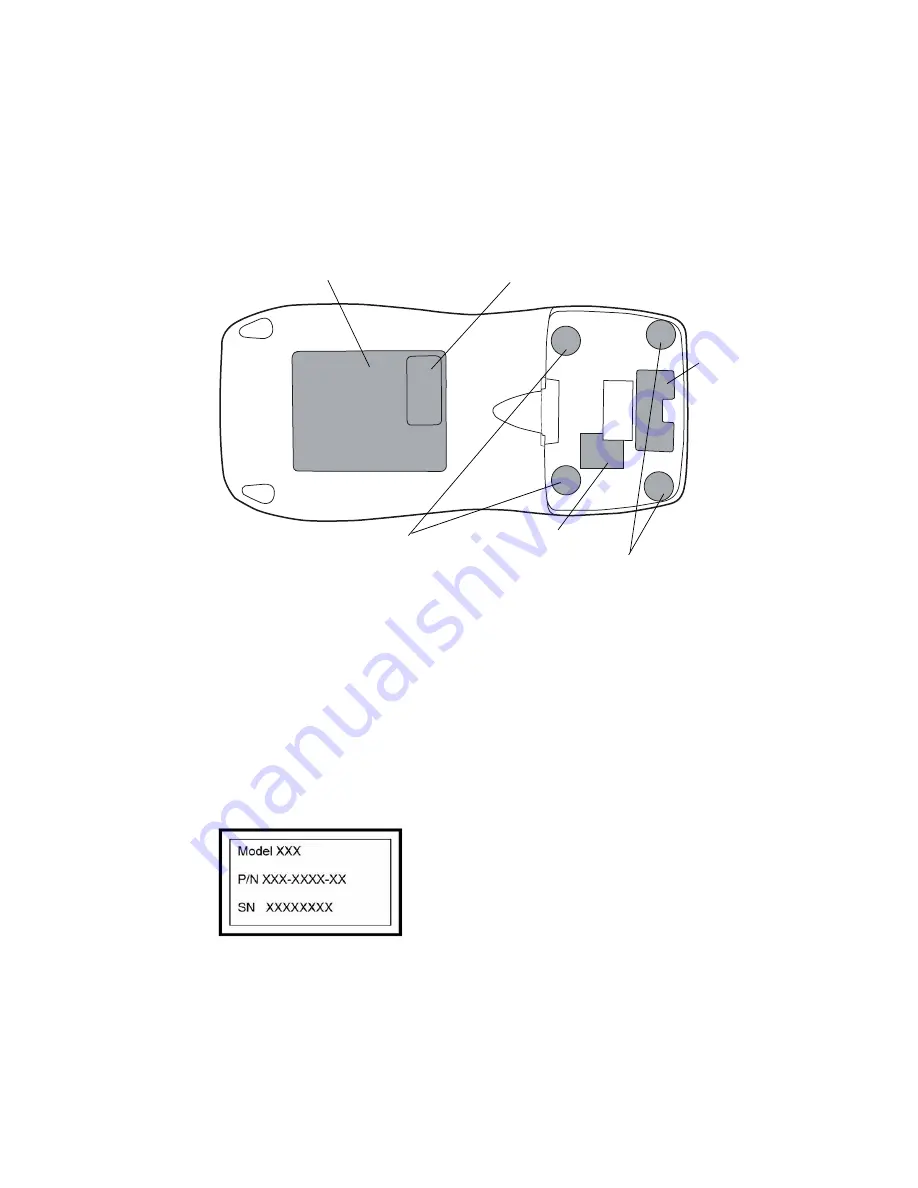
Most of the labels shown below are part of the service fastener kit. The clear serial 
number cover (not shown below) and the blank serial number label are included in the rear 
case service kit.

The rear case and battery well labels must be ordered separately.

1.

Apply the gray screw covers over the upper screw holes in the battery area.

2.

Apply the clear screw covers over the lower screws in the battery well.

3.

Apply the notched label over the small recessed connector next to the battery 
connector.

4.

Apply the rear case and battery well labels. 

5.

Apply the blank serial number label to the rear case label at the location shown above.

6.

Mark the blank serial number label with the model number, part number and serial 
number as shown below. Use an ultrafine point permanent marker. Write small to fit 
in all the required information.

7.

Apply the clear cover over the marked serial number label.

8.

Attach the battery and verify that:

the LED lights red, yellow and green,

no error messages are received,

the keyboard works.

Serial number label (blank)

Screw covers (clear)

Notched label (clear)

Screw covers (gray)

Rear case label

Battery well label

Summary of Contents for Micropaq 402

Page 1: ...Micropaq Monitor Service Manual Model 402 and Model 404 Software version 1 5X...

Page 2: ...such laws the licensee is entitled to use the copy of the software incorporated within this instrument as intended in the operation of the product in which it is embedded The software may not be copie...

Page 3: ...ctors Indicators and Controls 8 Indicators 9 Controls 9 Battery 10 Service Menu 10 Maintenance 10 3 Functional Verification 11 Visual Check 11 Power Up Test 12 System Test 12 ECG Test 14 SpO2 Test Mod...

Page 4: ...Case 35 Reassembly Model 404 37 Installing the Display 37 Installing the Main Board Subframe and Radio Card 39 Installing the SpO2 Board Masimo models 43 Installing the SpO2 Board Nellcor models 44 In...

Page 5: ...he monitor WARNING The Warning symbol indicates a condition that could lead to illness injury or death Caution The Caution symbol indicates a condition that could damage equipment or other property WA...

Page 6: ...ce has met all essential requirements of European Medical Device Directive 93 42 EEC for a Class 1 product battery charger kj Patient connections are Type CF isolated for direct cardiac application an...

Page 7: ...nds During equipment alerts silences or acknowledges dismisses the alert Scroll Up Key and Reset Alarm Tone Key Scrolls up menus on the display During patient alarms resets the tone at the monitor and...

Page 8: ...rap with a resistor of at least 1 megohm in series or other grounding device Use only grounded tools when inserting adjusting or removing static sensitive components and assemblies Remove or insert st...

Page 9: ...tive service is supported to the level of field replaceable units Field replaceable units include certain subassemblies service kits and other parts All field replaceable parts are listed in Field Rep...

Page 10: ...or service and monitor exchange policy Replace only fuses see procedure in this manual Contact Welch Allyn Technical Support for service and monitor exchange policy Calibration None required None requ...

Page 11: ...Obtain an RMA number for all returns to Welch Allyn Factory Service See Returning Products on page 6 Non Warranty Service Welch Allyn Beaverton factory service and authorized service centers support...

Page 12: ...ontrols SpO2 Connector ECG Connector Visual Alarm Indicator Liquid Crystal Display Battery Nurse Call Key Scroll Up Key and Reset Patient Alarm Tone Key Scroll Down Key and Main Menu Key Select Key an...

Page 13: ...Acuity Central Station Scroll Up and Reset Patient Alarm Tone Scrolls up menus on the display Resets a silenced patient alarm tone Scroll Down and Main Menu Scrolls down menus on the display Displays...

Page 14: ...off power While the battery is removed no monitoring occurs Recharge the battery while it is removed from the monitor To order a new battery contact Customer Service see page ii Service Menu Refer to...

Page 15: ...rify that the correct rear case label and battery label are attached b Verify that the serial number label is attached and that the correct information has been recorded for the model number part numb...

Page 16: ...ially blank for a few seconds that the LED displays each of the three colors red yellow and then green and that the monitor emits two short beeps while booting a quiet beep followed by a second louder...

Page 17: ...nd press again to run the highlighted display test 6 Press to exit the display test and return to the Display Test screen 7 Press again to exit the Display Test screen and return to the System Test sc...

Page 18: ...or lead and stops blinking when the switch is released 5 Disconnect the ECG cable from the simulator and monitor and then turn off power to the simulator Model 402 Testing is complete Remove the monit...

Page 19: ...ple Acuity systems to view the monitor select the system from the unit list that will be the primary link in the test If this is a single system or if the monitor is configured to communicate only wit...

Page 20: ...arger software The green LED by the ac power symbol at the far right side of the charger s top panel is on and that no other LED is on 4 Insert the battery into a battery well and confirm that the cor...

Page 21: ...charger Press it firmly and verify that it latches securely 7 Connect the ac power cord to the rear panel of the battery charger and to an ac power source appropriate for the power rating of the batte...

Page 22: ...to highlight SYSTEM INFORMATION and then press to display the System Information Menu 3 To access one of the menu items press or to highlight the menu item and press SpO2 Information Note Although th...

Page 23: ...the WLAN or the access points AP DROPPED MUs If nonzero indicates the number of times the monitor was forced off of the access point it was associated with Any nonzero value might indicate a problem...

Page 24: ...is associated RSSI Received Signal Strength Indicator indicates the strength in dB of the radio signal as seen by the associated access point The smaller the number the stronger the signal A value gre...

Page 25: ...actory defined names then the monitor displays the following screen Note This procedure applies only if the current net name is one of the names available in the Network Name Menu For other network na...

Page 26: ...monitor turns itself off and then turns on and seeks to connect to a FlexNet network with the new network name Changing a Custom Network Name If the current monitor network name is a custom name the...

Page 27: ...ns of the monitor only near connector J3 Add Kapton tape between the flex cable and the metalized subframe close to connector J3 Keyboard flex cable is damaged Check for sharp bends in the keyboard fl...

Page 28: ...ck for fractured solder joints on the ECG connector often caused by dropping the monitor Repair solder joints and retest the monitor Broken ECG flex cable Replace the appropriate front case assembly E...

Page 29: ...The monitor detects that at least one ECG electrodes is disconnected Check and replace or reconnect electrodes as needed NO ECG CABLE DETECTED If the ECG cable has been intentionally disconnected fro...

Page 30: ...26 Troubleshooting Welch Allyn Micropaq Monitor...

Page 31: ...Phillips screwdriver bit Tweezers Needlenose pliers Kapton tape Soft lens wipes Scissors or other cutting device Canned air Ultrafine point permanent marker Small paper clip Caution Perform all repai...

Page 32: ...annot be successfully connected or disconnected without properly unlatching and latching the sliding outer piece Disconnecting a ZIF Cable 1 Using a suitable tool for example a paper clip small flat h...

Page 33: ...ations Connector Main Board Description Connects with Referred to on J1 ZIF connector ECG flex cable External ECG connector flex cable page 34 J3 ZIF connector Keyboard flex cable Keyboard flex cable...

Page 34: ...del 404 37 Disassembly Model 402 49 Reassembly Model 402 53 Disassembly Model 404 This procedure covers the Masimo and Nellcor versions of the Model 404 monitor with SpO2 Opening the Case 1 Remove the...

Page 35: ...ith Disconnecting the SpO2 Board Nellcor models on page 33 Note If you are replacing only the rear case proceed to the gasket replacement step on Closing the Case on page 46 Note Do not damage the SpO...

Page 36: ...ard Masimo models 1 Slide the SpO2 board out from under the two bracket hooks 2 Lift the SpO2 board and disconnect the flex cables from connectors J1 and J3 3 Continue with Removing the Main Board Sub...

Page 37: ...ecting the SpO2 Board Nellcor models 1 Unplug the flex cables from connectors J1 and J2 2 Slide the SpO2 board out from under the two bracket hooks shown at left in the illustration below 3 Remove the...

Page 38: ...rd Subframe and Radio Card all models 1 Unplug the SpO2 flex cable at connector J11 2 Unplug the ECG sensor cable at connector J1 3 Remove the screws and rectangular washers from the SpO2 shield SpO2...

Page 39: ...rubber cushions b Carefully slide the display out from under the soldered connections c Pry up the rubber cushions closest to the connectors and remove the display Caution Do not separate the main bo...

Page 40: ...shions 3 Set the display down on a clean surface with the circuit board side facing up Caution Do not bend or stress the display flex cable especially at its connection to the circuit board Caution Do...

Page 41: ...he protective plastic liner from the front of the display Note The first two steps apply only if you are installing a new display If you are reusing a display skip to step 3 on page 38 Caution The dis...

Page 42: ...efully slide the display under the soldered connections c Press the rubber cushions farthest from the connectors into place 5 Carefully bend the display flex cable so that it curves back toward the ci...

Page 43: ...connector and lock the latching piece refer to Zero Insertion Force ZIF Connectors on page 28 for complete ZIF connector installation instructions Caution The display flex cable is fragile Damage may...

Page 44: ...the front case 6 Insert the keyboard cable into the J3 connector and lock the latching piece Note Tilt the assembly slightly toward the connectors as shown to allow insertion of the display flex cabl...

Page 45: ...ice Manual Repair Procedures 41 7 Insert the ECG sensor cable into the J1 connector and lock the latching piece Smooth curve in flex cable Correct Incorrect Sharp bend in flex cable ECG sensor cable a...

Page 46: ...the front case Torque the screws to 3 in lbs 10 For Masimo models continue with the next section For Nellcor models continue with Installing the SpO2 Board Nellcor models on page 44 Caution The pin on...

Page 47: ...s installation of the SpO2 board on Masimo models For Nellcor models go to Installing the SpO2 Board Nellcor models on page 44 1 Attach the SpO2 sensor cables to connectors J1 and J3 2 Seat the SpO2 b...

Page 48: ...Welch Allyn Micropaq Monitor Installing the SpO2 Board Nellcor models 1 Carefully slide the SpO2 board under the two bracket hooks as shown 2 Plug the SpO2 cables into connectors J1 and J2 Bracket hoo...

Page 49: ...3 in lbs 4 Place metal washers and screws in the locations shown below and torque to 3 in lbs Caution Take care to place the nylon washer s in the correct location s or the system will not operate pr...

Page 50: ...ach the battery and verify that Caution Do not stretch the gasket Stretching the gasket will make reassembly more difficult and may result in a poor seal between the front and rear case Note Both ends...

Page 51: ...ront and rear cases during reassembly 7 Screw the rear case to the front case making sure the rubber gasket stays in its groove Torque the screws as shown in the illustration below 8 Push the rubber f...

Page 52: ...l over the small recessed connector next to the battery connector 4 Apply the rear case and battery well labels 5 Apply the blank serial number label to the rear case label at the location shown above...

Page 53: ...overs the Model 402 monitor with ECG only Opening the Case 1 Remove the battery pack 2 Remove the rubber feet from the rear panel 3 Remove the six case screws 4 Separate the case Note If you are repla...

Page 54: ...bframe and Radio Card 1 Unplug the ECG sensor cable at connector J1 2 Remove the screws and rectangular washers from the subframe 3 Unplug the display cable from connector J4 and keyboard cable from c...

Page 55: ...c Pry up the rubber cushions closest to the connectors and remove the display 2 If you are installing a new display remove and save the rubber cushions 3 Set the display down on a clean surface with t...

Page 56: ...lyn Micropaq Monitor Caution Do not bend or stress the display flex cable especially at its connection to the circuit board Caution Do not touch the display screen Fingerprints are difficult to remove...

Page 57: ...ective plastic liner from the front of the display Note The first two steps of this section apply only if you are installing a new display If you are reusing a display skip to step 3 on page 54 Cautio...

Page 58: ...lly slide the display underneath the soldered connections c Press the rubber cushions farthest from the connectors into place 5 Carefully bend the display flex cable so that it curves back toward the...

Page 59: ...play cable to the J4 connector and lock the latching piece refer to Zero Insertion Force ZIF Connectors on page 28 for complete ZIF connector installation instructions Caution The display flex cable i...

Page 60: ...Place the main board into the front case 6 Insert the keyboard cable into the J3 connector and lock the latching piece Note Tilt the assembly slightly toward the connectors as shown to allow insertio...

Page 61: ...bs Closing the Case 1 Insert the rubber gasket part of the fastener kit into the groove in the front case Begin inserting the gasket in the end locking section located on the lower edge of the case as...

Page 62: ...g the gasket will make reassembly more difficult and may result in a poor seal between the front and rear case Note Both ends of the gasket should extend as far as possible into the end locking sectio...

Page 63: ...e the rubber gasket stays in its groove Torque the screws as shown in the illustration below 7 Push the rubber feet into the rear case For ease of installation apply a small amount of alcohol to the r...

Page 64: ...l over the small recessed connector next to the battery connector 4 Apply the rear case and battery well labels 5 Apply the blank serial number label to the rear case label at the location shown above...

Page 65: ...er motion and low perfusion conditions Micropaq 404 only Two way wireless communication within Welch Allyn s FlexNet network LCD for display of ECG waveforms SpO2 and heart rate pulse rate data and me...

Page 66: ...During monitoring the monitor sends the patient data to Acuity Acuity and the monitor continuously analyze the data Acuity provides appropriate alarm or alert messages at the Central Station and other...

Page 67: ...el 640 0513 04 Label Rear Batt Well Sheet Masimo Micropaq 404 with Masimo 640 0540 02 Label Rear Batt Well Sheet Nellcor Micropaq 404 with Nellcor 640 0600 XX Label Rear Battery Well Sheet ECG Only Mi...

Page 68: ...64 Field Replaceable Units Welch Allyn Micropaq Monitor...

Reviews: