background image

6.1.3  Connecting an energy optimization system

Purpose of an energy optimization system

You can connect the combi oven to an energy optimization system (e.g. SICOTRONIC). An energy optimization system
smooths out peaks in power consumption that occur during operation of your appliances, and can thereby help to reduce
your energy costs.

Configuring an energy optimization system

The energy optimization system must be configured as follows:

The connecting lines between the appliance and the energy optimization system should not be longer than 5 m. If this is

not possible, the connection must be carried out using an intermediate relay located at a maximum distance of 5 m from

the appliance.

The continuous switch-on time for the combi oven must be set to at least 8 minutes to be certain that the target cooking

temperature is reached.

The energy optimization system must not disconnect the power for longer than 30 seconds because the cooking result

cannot be guaranteed for a longer interruption in the power supply.

When connecting the system, refer to the circuit diagram and operating instructions of the energy optimization system.

Accessories required

You need the following parts to connect the energy optimization system:

Connecting cable for energy optimization system

Cable gland M20

Cable ties

Connecting an energy optimization system

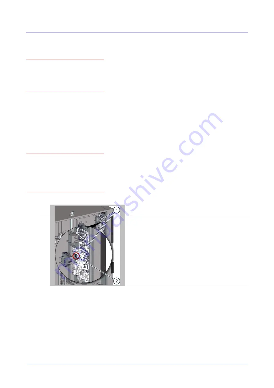
The figure below shows a size 12.20 combi oven as an example for all appliance sizes:

1.

Disconnect the energy optimization system and the combi oven from

the power supply.

2.

Remove the side panel from the combi oven in order to access termi-

nal block -X37 (2) on the system interface board (SIB) (1) in the area

behind the operating panel.

6 Installation

Installation manual

43

Summary of Contents for C4 EB 12.20

Page 1: ...Combi oven Convotherm 4 C4 floor standing units Installation manual Original ENG Advancing Your Ambitions ...

Page 2: ......

Page 3: ...of delivery 29 5 Setting up the appliance 30 5 1 Adjacent systems 30 5 2 Requirements for the installation location 31 5 3 Taking the appliance off the pallet 35 5 4 Setting up a floor standing unit on the floor standard model 38 5 5 Setting up a floor standing unit on the floor marine model 39 6 Installation 40 6 1 Electrical installation 40 6 1 1 Planning the electrical installation 40 6 1 2 Car...

Page 4: ...ion natural gas 2H E natural gas 2L LL propane 3P liquefied gas 3B P 86 9 10 Gas specification The Netherlands 87 9 11 Gas specification Australia New Zealand 88 9 12 Gas specification Japan 89 9 13 Gas specification Korea 89 9 14 Gas consumption 90 9 15 Exhaust gas output rate 90 9 16 Heat output natural gas 2H E natural gas 2L LL propane 3P liquefied gas 3B P 91 9 17 Heat output The Netherlands ...

Page 5: ...10 9 Convotherm 4 20 20 injection gas appliance 117 Table of Contents Installation manual 5 ...

Page 6: ...mental management system in order to guarantee the continued manufacture of high quality products and to be sure of meeting our environmental targets This system satisfies the requirements of ISO 9001 2015 and ISO 14001 2015 Environmental protection procedures We observe the following procedures Use of residue free compostable wadding materials Use of RoHS compliant products REACH chemical law Rec...

Page 7: ... numbers xx yy Appliance size EB Electric appliance with boiler ES Electric appliance with water injection N for appliances with an NSF certificate 3 Electrical values 4 Certification marks 5 Serial number Element Meaning Heating method Electric appliance X Steam generation method Injection S Boiler B Appliance size 12 20 5 20 10 6 20 20 7 Year of manufacture 2021 21 2022 22 Month of manufacture J...

Page 8: ...injection N for appliances with an NSF certificate 3 Electrical values 4 Certification marks 5 Serial number Element Meaning Heating meth od Gas appliance Y Steam genera tion method Injection S Boiler B Appliance size 12 20 5 20 10 6 20 20 7 Year of manu facture 2021 21 2022 22 Month of man ufacture January 01 February 02 March 03 Sequential number 4 digits 6 Part number 7 Gas data 8 Country code ...

Page 9: ...cting the user Owner of the combi oven or owner s member of staff who is responsible for the appli ance and for the operating personnel Made aware of all safety related functions and devices of the combi oven by the start up engineer Instructed by the start up engineer on how to operate the appliance Provides assistance as instructed with conveying the appliance within the establishment and settin...

Page 10: ...must always be observed when performing tasks that go beyond merely operating the software Parts of this document that must be read without fail If you do not follow the information in this document you risk potentially fatal injury and property damage To guarantee safety all people who work with the combi oven must have read and understood the following parts of this document before starting any ...

Page 11: ...ance door On latch position for opening the appliance safely Antibacterial material containing silver ions HygieniCare 5 Operating panel Used for operating the appliance Antibacterial HygieniCare 6 Suction panel Distributes the heat evenly inside the cooking chamber Separates the fan compartment from the cooking chamber 7 Cooking chamber Contains the food during cooking operation 8 Built in prehea...

Page 12: ...or all gas appliances Item Name Function 1 Ventilation port External air intake for removing the moisture from the cooking chamber Smooths out any pressure fluctuations in the cooking chamber 2 Exhaust outlet Takes away hot exhaust gases 3 Air vent Allows hot vapour to escape 4 Appliance door Closes the cooking chamber Can slide back beside the appliance when opened in order to save space disappea...

Page 13: ... the appliance wiring compartment Components and function of the special security mechanism prison model only The following illustration shows the optional special security mechanism for a size 6 10 gas combi oven as an example of all appliance sizes Item Name Function 1 Lockable cover to the operating panel The hinged cover can be closed over the operating panel and locked to the ap pliance case ...

Page 14: ...he control panel full touch screen display Status displays Layout and elements of the easyDial operating panel Item Name Function 1 Appliance ON OFF switch Switches the combi oven on and off 2 Control panel Central controls for appliance Buttons for entering the cooking programs Displays showing the values you have set Prompts for the user 3 USB port For connecting a USB stick 4 C Dial Combined ro...

Page 15: ...t comply with all national and regional laws and regulations and comply with the local regulations of the rele vant utility companies and local authorities and with other relevant requirements In Australia and New Zealand these regulations also include amongst other regulations AS 5601 AG 601 Working with the combi oven Follow the instructions below Only those persons who satisfy the requirements ...

Page 16: ... properly in place The manufacturer regulations for operating and servicing the combi oven must be observed The combi oven must not be loaded over the maximum permissible loading weight for the given model or shelf allow ance see Technical Data on page 74 Requirements relating to the operating environment of the combi oven Specified operating environment for the combi oven The ambient temperature ...

Page 17: ...a risk of scalding from hot steam and vapour escaping when the appliance door is opened 2 and 3 Standard model Warning of hot liquids Spillage of hot liquid foods can result in scalds if the upper shelf levels are loaded with liquids or with foods that produce liquid during cooking Do not use shelf levels that lie above your sightline for liquid foodstuffs or food that will liquefy during cook ing...

Page 18: ...g over if moved Always take great care when moving the loading trolley When moving the loading trolley watch out for ob jects in the way or unevenness in the floor 4 only for the prison model Hot surface hazard warning Risk of burns from hot surfaces on the handle of the loading trolley 3 For your safety Installation manual 18 ...

Page 19: ...ded Before starting any work the appliance must be disconnected from the power supply protected against being switched on again and checked to verify that it is actually de energized After de energization has been ascertained a waiting time of at least 15 minutes is mandatory to allow full discharge of the DC bus capacitors To ensure operational and functional safety all electrical connections mus...

Page 20: ...hat to do if you smell gas on page 69 Escaping gas when installing the appliance and removing the appliance from service Escaping gas due to faulty installation and removal of the appliance from service can cause the following hazards Explosion hazard from gas What can cause this If gas pipes are leaking If the customer s gas tap is opened before the gas connection has been fully installed During ...

Page 21: ...ssing your body When When moving or lifting the appliance How can I avoid the hazard Use a forklift truck or pallet truck to place the appliance in the installation position or to move it to a new position Always use the correct number of persons and observe the limits specified for lifting and carrying when adjusting the appliance position guide value 15 to 55 kg max depending on age and gender O...

Page 22: ...the appliance and on adjacent metallic accessories How can I avoid the hazard Before preparing the appliance for first time use make sure that the appliance including all metallic accessories is connected to a equipotential bonding system Contact with cleaning agents The following hazards can arise at the appliance when performing any installation work Risk of chemical burns or irritation to skin ...

Page 23: ...g touched accidentally Ensure that the operating panel is in place 3 Appliance door Protects the user and outside envi ronment from hot steam Check the door pane regularly for scratches cracks indentations etc and replace it if any are found 4 Suction panel in cooking chamber can only be re moved using a tool Prevents access to the moving fan wheel s and ensures good heat dis tribution See Releasi...

Page 24: ...rvicing work and in a hazardous situation Action Close gas shut off device Check that the appliance is isola ted from the gas supply Safety measures The following measures increase the safety additionally Measure Function Check Magnetic switch for appli ance door electric door sen sor When the appliance door is opened the switch stops rotation of the fan wheel comes to a stop after a few seconds o...

Page 25: ...ctly Setting up the appliance Installing the fully automatic oven cleaning system Putting the appliance into service Removing the appliance from service Gas installation engi neer Is a gas installation engineer authorized by the gas utility company Has relevant professional training Is an employee of an authorized service com pany Connecting the appliance to the building s gas supply Disconnecting...

Page 26: ...alling the appliance and putting the appliance into service The working position for personnel installing the appliance and putting the appliance into service is the entire appliance area 3 For your safety Installation manual 26 ...

Page 27: ...e fully automatic oven cleaning system Tools and equipment depend on the task Items of protection equipment depending on cleaning agent being used Breathing mask Safety goggles Protective gloves Protective clothing apron The EC safety datasheet for the relevant cleaning agent contains a more precise specification of these items An up to date copy can be obtained from the manufactur er Refer to the...

Page 28: ... the weight of the appliance including packaging to determine the minimum working load limit of handling equipment see Dimensions and weights Technical data on page 74 Conveying the appliance to the installation location for the first time Please observe the following points when conveying the appliance Always move the appliance on a pallet Always move the appliance in an upright position Use a fo...

Page 29: ... hose for rinse aid optional 1x empty canister for extracted grease grill version 1x connecting tube with attached screw cap for grease collecting canister grill version Documentation The following documents are supplied with the appliance 1x Installation manual 1x User manual hardware 1x Operating instructions software 1x Unpacking instruction leaflet 1x Checklist for installation and putting int...

Page 30: ...dance from the local building authority for fume extraction systems Dealing with exhaust gases for gas appliances Exhaust gases at a temperature of up to 500 C escape from the exhaust outlet s on the top of the combi oven into the surrounding air It is not permitted to connect pipes directly to an exhaust outlet of the combi oven as a way of removing the exhaust gases It is mandatory to use a vent...

Page 31: ...s or appliances that use hot uncovered fat Deep fat fryers or applian ces that use hot uncovered fat that are located in the vicinity must lie at a minimum distance of 1600 mm Do not install the appliance directly under a fire alarm or sprinkler system Fire alarm installations and sprinkler systems must be set up to handle the level of steam and vapour expected to escape from the appliance It must...

Page 32: ... of the appliance Ventilation holes in the appliance floor Space required for right hinged door width and depth The following diagram and table show the space required for the appliance for different installation and operating situations They also show the minimum horizontal distances from adjacent walls and surfaces The safety clearances on the left right and rear must always be complied with 90 ...

Page 33: ... S3 12 20 20 10 20 20 Meaning B1 Width requirement appliance door open at 90 mm 1338 1094 1338 B2 Width requirement appliance door open at 180 mm 2010 1560 2010 B3 Width requirement disappearing door retracted mm 1345 1100 1345 R Space required on right hand side disappearing door retracted mm 160 160 160 T Depth requirement when opening the appliance door mm 1860 1455 1860 S1 Safety clearance on ...

Page 34: ...n system vapour extractor hood etc when designing the particular clear ance needed between the top of the appliance and the ceiling In this context the vertical distance H1 must be understood as a guide value for the minimum vertical clearance 12 20 20 10 20 20 Meaning Electric appliances H1 Guide value for the minimum vertical clearance mm 500 500 500 Gas appliances H1 Guide value for the minimum...

Page 35: ... keep the appliance balanced Taking the appliance off the pallet standard model 1 On one side of the appliance place the slides on the green markers with the safety lip facing outwards in each case Make sure that you push each slide right up against the pallet so that the screws have suffi cient material to screw into 2 Screw the two slides onto the pallet 3 Remove all the screws from the slide bl...

Page 36: ...ff the side of the slide Be careful when transferring the appliance from the slide onto the non slip floor Use at least two people to slide the appliance on the slide blocks down the slides and onto the floor to the installation location 5 Lift up the combi oven slightly and remove the slide blocks 6 Remove the protective plastic from the combi oven 5 Setting up the appliance Installation manual 3...

Page 37: ...he appliance To protect the wheel in rail 1 for the loading trolley insert two lengths of wood underneath the appliance according to the type of lifting gear you are using and the side from which you are lifting the appliance 3 Move the appliance carefully off the pallet to the installation location 4 Remove the protective plastic from the combi oven 5 Setting up the appliance Installation manual ...

Page 38: ... must be possible to wheel the loading trolley up to the cooking chamber on a flat surface that is clear of obstructions Setting up the appliance 1 Position the appliance on the floor 2 Ensure the appliance is horizontal by adjusting the height of the appli ance feet Use a spirit level to ensure the unit is horizontal in all directions Make sure that the loading trolley can move freely into the ap...

Page 39: ...face that is clear of obstructions Setting up the appliance 1 Place the appliance in position and fix the four flanged feet perma nently to the floor by screw fastening or welding 2 Ensure the appliance is horizontal by adjusting the height of the appli ance feet Use a spirit level to ensure the unit is horizontal in all directions Make sure that the loading trolley can move freely into the applia...

Page 40: ... of the appliance must comply with local regulations and national installation requirements Protective equipotential bond ing system The appliance must be incorporated in a protective equipotential bonding system Protective equipotential bonding system Electrical connection that ensures that the frames of electrical equipment and any external conductive components are at an equal or practi cally e...

Page 41: ...p characteristic for RCD devices with trip threshold 30 mA prevents RCD being tripped by charging currents of capacitors and parasitic capacitances when appliance is switched on Leakage current protection type SI trip characteristic for RCD devices with trip threshold 30 mA insensitive to nuisance tripping Mains supply connection The power cord must be an oil resistant sheathed and flexible cable ...

Page 42: ...s tally with each other 3 Check all screw connections and terminals on the appliance The connections may have worked loose during transport Carrying out the electrical installation The figure below shows a size 12 20 combi oven as an example for all appliance sizes 1 Remove the side panel from the appliance 2 Connect the appliance to a protective equipotential bonding system at the designated conn...

Page 43: ...t least 8 minutes to be certain that the target cooking temperature is reached The energy optimization system must not disconnect the power for longer than 30 seconds because the cooking result cannot be guaranteed for a longer interruption in the power supply When connecting the system refer to the circuit diagram and operating instructions of the energy optimization system Accessories required Y...

Page 44: ...ing har ness 4 Remove the wire link between the terminals B and C on terminal block X37 2 5 Connect the terminals A B C and D of terminal block X37 2 to the energy optimization system Terminal Combi oven Energy optimization system A Phase when combi oven is on B Phase when combi oven heating element is on Switching relay C Heater enable B and C must be connected by switching relay in the ener gy o...

Page 45: ...ed the following equipment Cable ties Connecting the signal tower The figure below shows a size 12 20 combi oven as an example for all appliance sizes 1 Disconnect the combi oven from the power supply 2 Remove the side panel from the combi oven in order to access termi nal block X32 2 on the system interface board SIB 1 in the area behind the operating panel 3 Tap out the larger pre perforated kno...

Page 46: ...nt shown below PIN Assignment Wire colour 1 GND BU Blue 2 Signal buzzer GY Grey 3 Signal red light BK Black 4 Signal yellow light WH White 5 Signal green light BN Brown 5 Refit the side panel on the combi oven 6 Put the combi oven and signal tower into operation 6 Installation Installation manual 46 ...

Page 47: ...he water treatment filter monitor The figure below shows a size 12 20 combi oven as an example for all appliance sizes 1 Disconnect the combi oven from the power supply 2 Remove the side panel from the combi oven in order to access termi nal block X33 2 on the system interface board SIB 1 in the area behind the operating panel 3 Tap out the larger pre perforated knock out in the floor panel of the...

Page 48: ...ter monitor to the combi oven in accordance with the PIN assignment shown below PIN Assignment 1 Signal 2 GND 5 Refit the side panel on the combi oven 6 Put the combi oven and water treatment filter monitor into operation 6 Installation Installation manual 48 ...

Page 49: ...int J in the connection drawing The appliance must be secured in place Gas shut off device A gas shut off device must be fitted close to the appliance The gas shut off device must be easily accessible and situated so that it can also be shut off in a hazardous situation Pressure regulator A pressure reducer must be fitted if the supply flow pressure is too high All connection components All connec...

Page 50: ...Exhaust gas temperature The temperature of the undiluted exhaust gas can reach 500 C Follow fire safety regulations 6 Installation Installation manual 50 ...

Page 51: ...0 combi oven gas appliance with boiler Item Name 1 Exhaust outlet from boiler burner only on models with boiler not steam injection 2 Exhaust outlet for convection burner 3 Convection burner 4 Main gas valve connection to gas supply in appliance floor 5 Boiler burner only on models with boiler not steam injection 6 Installation Installation manual 51 ...

Page 52: ...em Name 1 Exhaust outlet from boiler burner only on models with boiler not steam injection 2 Exhaust outlet for bottom convection burner 3 Exhaust outlet for top convection burner 4 Top convection burner 5 Bottom convection burner 6 Main gas valve connection to gas supply in appliance floor 7 Boiler burner only on models with boiler not steam injection 6 Installation Installation manual 52 ...

Page 53: ...onnections that are not gastight 7 Start a cooking profile in the Convection operating mode 8 Measure the supply flow pressure at the gas valve Result If the supply flow pressure is higher than the specified range it may be possible to reduce the level If the supply flow pressure is lower than the specified range then you as gas fitter will not be able to correct this If the measured value lies wi...

Page 54: ...ressure 1 Measure the supply flow pressure at the valve 1 of the gas valve on the fan burner 2 Compare the measured value with the specified limits see Data for gas operation in Technical data on page 74 Result If the measured supply flow pressure is lower than the specified val ues Notify the gas provider In this case the appliance must not be put into use and the gas supply must be switched off ...

Page 55: ...ead ings Additional information If the meter indicates approx 21 O2 or nothing at all then the sensor is inside the wrong exhaust outlet 3 Wait 1 minute before taking the readings 4 and then compare them with the specified limit see Data for gas operation in Technical data on page 74 If the reading does not lie within the limit the appliance much be checked as directed in the adjustment instructio...

Page 56: ...es relating to the network connection The table below shows what equipment must be provided by the customer and what regulations must be observed when connecting the appliance Equipment Rules RJ45 network socket There must be a network connection for the combi oven installed close to the appliance When connecting more than one combi oven a dedicated network connection must be in stalled for each a...

Page 57: ...e installed and given clearance for use 2 When putting the combi oven into service check whether the KitchenConnect Internet icon in the user interface indicates that the connection is enabled Checking the network connection Display in easyTouch Button Meaning KitchenConnect blue Internet is enabled installation successful KitchenConnect white Internet is disabled installation unsuccessful 6 Insta...

Page 58: ...ew connection Water quality and water hardness Find out the water quality and water hardness from your local water supply company or test the water quality as descri bed in Testing the water quality on page 62 Information on the required drinking water quality is given in the Technical Data chapter under the Water quality head ing If necessary provide suitable water treatment measures For instance...

Page 59: ...nking water X 0 08 mm sediment filter A 0 08 mm sediment filter must be installed if the water has a high level of impurity Y Shut off device Water tap V Suitable backflow preventer only required for steam injectors where there is an NSF requirement otherwise optional The appliance must be installed with suitable backflow protection to comply with applicable federal state and local codes DCV Doubl...

Page 60: ...talled if the water has a high level of impurity W Water treatment for softening the water to the required soft water quality Recommendation Partial demineralization cartridge Y Shut off device Water tap V Suitable backflow preventer only required for steam injectors where there is an NSF requirement otherwise optional The appliance must be installed with suitable backflow protection to comply wit...

Page 61: ...check valve DCV are required see connection diagram fit the relevant device in the water supply line 5 Connect the appliance as shown in the connection drawing 6 Flush through the sediment filter by operating the recoil hand shower 7 Once the water supply has been installed close the shut off device 8 Inform the user about the service intervals for the filters and the water treatment system if app...

Page 62: ...eral hardness and carbonate hardness including two analysis containers part no 3019010 Protective gloves Test the water quality Measure the electrical conductivity and general hardness of the water By following the instructions included with the tester and analysis kit Compare the measured values with the recommended values see Technical data on page 74 6 Installation Installation manual 62 ...

Page 63: ...must be no restriction or reduction in the cross section of the drain pipe The slope of the drain pipe must equal min 3 5 2 If more than one appliance is connected to one drain pipe this pipe must be large enough to allow the wastewater to flow out unchecked The appliance must be connected to the drain using a NON flexible pipe Drainage into an open tub or channel is recom mended alternatively a f...

Page 64: ...cted cannisters Item Name Colour cod ing F Appliance connector for rinse aid supply green letter ing G Appliance connector for cleaning agent supply red lettering 1 Canister containing ConvoCare rinse aid ready to use solution in defined mixing ratio green label 2 Delivery tube for rinse aid suction nozzle green tube 3 Canister containing ConvoClean new or ConvoClean forte red label 4 Extractor tu...

Page 65: ...should be located for easy access beside the appliance on a flat surface The surface on which the canister sits must not lie above the level at which the appliance feet meet the appliance case The surface on which the canister sits must not lie more than 1 metre below this level 6 Installation Installation manual 65 ...

Page 66: ...re rinse aid in the canister 2 Plug the green extractor tube 2 for the ConvoCare rinse aid onto the connector nipple of the rear tube fitting F and secure the tube in place with the wire clip 3 see label for rinse aid connection on the left hand side of the appliance 3 Insert the suction nozzle on the green extractor tube 2 into the rinse aid canister 1 There must be no kinks in the tube and the v...

Page 67: ...ecure the tube in place with the wire clip 3 see label for cleaning agent connection on the left hand side of the appli ance 5 Insert the suction nozzle on the red extractor tube 4 into the clean ing agent canister 5 There must be no kinks in the tube and the vent hole in the canister must be open and unblocked 6 Installation Installation manual 67 ...

Page 68: ...eath the combi oven and secure the tube 2 with the hose clip 3 3 Screw the canister screw cap 4 attached to the connecting tube 2 onto the grease collecting canister 5 4 Place the grease collecting canister 5 in a suitable position and make sure there are no kinks in the connecting tube 2 5 Fix the forked bracket 6 within reach of the outlet pipe 1 This bracket will be used to hold the canister sc...

Page 69: ...appliance and fittings or accessories being used show no signs of damage The installed electrical power cables water supply pipes and pipes for wastewater and cleaning products show no signs of damage are fixed securely are not leaking from any point and appear safe and in working order on visual inspection The Requirements relating to the operating condition of the combi oven on page 16 are met T...

Page 70: ...s are in their designated position The appliance and any accessories and fitting used have been cleaned properly The appliance must not be put into operation until all the specified requirements are met Individual electrical test The individual electrical test comprises the following three steps Observation Visual inspection for damage or improper use Measurement Carry out prescribed measurements ...

Page 71: ...ing the cleaning profile for light soiling 7 Check that the cleaning process runs without an error message Customer guidance and instruction Instruct the user in all safety related functions and devices Instruct the user in how to operate the appliance and complete the checklist supplied with the appliance Warranty information In order to be able to claim under the warranty for the combi oven the ...

Page 72: ...aps must lie within the following tolerance ranges Name Measurement condition Tolerance range Door gap at the front of the appliance The appliance door is closed 10 1 mm If the door gap does not lie within tolerance please contact Customer service 7 Putting into service Installation manual 72 ...

Page 73: ...onnected all the connections The following tasks must be performed correctly to remove the appliance from service Disconnecting the water connection from the appliance Removing the drain connection from the appliance Disconnecting or isolating the electrical supply Disconnecting the gas supply from the appliance Disconnecting the exhaust gas extraction system Removing the door catch Disconnecting ...

Page 74: ... mm 50 50 50 Left larger gap recommended for servicing mm 50 50 50 Top for ventilation mm 500 500 500 C4 GB GS dimensions 12 20 20 10 20 20 Appliance including packaging Width mm 1410 1165 1410 Height mm 1615 2150 2150 Depth mm 1170 970 1170 Appliance excluding packaging Width for appliance with right hinged appliance door mm 1135 890 1135 Width for appliances with disappearing door inclusive of g...

Page 75: ...d door kg 241 257 338 Disappearing door kg 252 277 358 Weight of packaging Weight of packaging kg 45 40 48 C4 GB weights 12 20 20 10 20 20 Weight excluding packaging without ConvoClean ConvoClean Right hinged door kg 287 281 370 Disappearing door kg 298 301 390 with ConvoClean ConvoClean Right hinged door kg 293 288 377 Disappearing door kg 304 308 397 Weight of packaging Weight of packaging kg 45...

Page 76: ...missible loading weight C4 EB ES GB GS The total weight of items placed on the shelf levels must not exceed the maximum permissible loading weight of the combi oven 12 20 20 10 20 20 Maximum load Per combi oven kg 120 100 180 Per shelf kg 15 15 15 9 Technical data Installation manual 76 ...

Page 77: ... 5 Motor power kW 0 35 0 7 0 7 Rated current A 48 7 56 2 97 3 Fuse rating A 50 63 100 Residual current mA Protective earth current mA Recommended conductor cross section for wires laid uncovered in air up to 5 m in length mm2 5G16 5G16 5G35 Residual current device Type B B B C4 EB single phase FC 12 20 20 10 20 20 3N 400V 50 60Hz 3 N PE Rated power consumption kW 33 7 38 9 67 3 Convection power kW...

Page 78: ... 3 38 1 66 5 Motor power kW 0 35 0 7 0 7 Rated current A 48 7 56 2 97 3 Fuse rating A 50 63 100 Residual current mA 7 5 16 5 16 5 Protective earth current mA 7 5 16 5 16 5 Recommended conductor cross section for wires laid uncovered in air up to 5 m in length mm2 5G16 5G16 5G35 Residual current device Type A B A B A B 3 230V 50 60Hz 3 PE Rated power consumption kW 33 4 38 2 66 4 Convection power k...

Page 79: ...aid uncovered in air up to 5 m in length mm2 3G2 5 3G2 5 3G2 5 Residual current device Type A B A B A B C4 GS single phase FC 12 20 20 10 20 20 1N 230V 50 60Hz 1 N PE Rated power consumption kW 0 6 1 1 1 1 Convection power kW 0 1 0 2 0 2 Motor power kW 0 35 0 7 0 7 Rated current A 2 3 4 3 4 3 Fuse rating A 16 16 16 Residual current mA 11 5 15 0 Protective earth current mA 91 0 Recommended conducto...

Page 80: ...66 0 Steam power EB only kW 31 3 31 3 39 9 Motor power kW 0 35 0 7 0 7 Rated current A 96 6 110 4 191 9 Fuse rating A 100 125 200 Residual current mA Protective earth current mA Recommended conductor cross section for wires laid uncovered in air up to 5 m in length mm2 4G35 4G50 4G95 Residual current device Type A B A B A B 9 Technical data Installation manual 80 ...

Page 81: ...s laid uncovered in air up to 5 m in length mm2 4G35 4G35 4G70 Residual current device Type A B A B A B 3N 380V 60Hz 3 N PE Rated power consumption kW 30 5 35 1 60 7 Convection power kW 30 1 34 4 60 0 Steam power EB only kW 28 5 28 5 36 3 Motor power kW 0 35 0 7 0 7 Rated current A 46 3 53 3 92 2 Fuse rating A 50 63 100 Residual current mA 7 5 16 5 16 5 Protective earth current mA 7 5 16 5 16 5 Re...

Page 82: ...ted current A 2 7 4 7 4 7 Fuse rating A 16 16 16 Residual current mA 11 5 Protective earth current mA Recommended conductor cross section for wires laid uncovered in air up to 5 m in length mm2 3G2 5 3G2 5 3G2 5 Residual current device Type A B A B A B C4 GS single phase FC 12 20 20 10 20 20 1N 120V 60Hz Rated power consumption kW 0 5 1 0 1 0 Convection power kW 0 1 0 2 0 2 Motor power kW 0 4 0 7 ...

Page 83: ...A 16 16 16 Residual current mA 11 5 15 0 Protective earth current mA Recommended conductor cross section for wires laid uncovered in air up to 5 m in length mm2 3G2 5 3G2 5 3G2 5 Residual current device Type A B A B A B 9 Technical data Installation manual 83 ...

Page 84: ... 7 Rated current A 40 3 46 5 80 5 Fuse rating A 50 50 100 Residual current mA Protective earth current mA Recommended conductor cross section for wires laid uncovered in air up to 5 m in length mm2 4G16 4G16 4G35 Residual current device Type B B B C4 ES three phase FC 12 20 20 10 20 20 3 440V 50 60Hz Rated power consumption kW 28 2 32 6 56 3 Convection power kW 27 8 31 8 55 5 Motor power kW 0 35 0...

Page 85: ...use rating A 50 50 100 Residual current mA Protective earth current mA Recommended conductor cross section for wires laid uncovered in air up to 5 m in length mm2 4G16 4G16 4G35 Residual current device Type B B B 9 Technical data Installation manual 85 ...

Page 86: ...0 25 57 5 Gas data as per CE at 15 C and 1013 mbar dry Lower Wobbe Index Wi MJ m3 45 7 36 8 49 6 37 4 30 9 40 5 70 7 68 1 70 7 80 6 68 1 80 6 Upper Wobbe Index WS MJ m3 50 7 40 9 54 7 41 5 34 4 44 8 76 8 72 9 76 8 87 3 72 9 87 3 Lower calorific value Hi MJ m3 34 29 3 88 116 1 MJ kg 46 3 45 7 Higher calorific value HS MJ m3 37 8 32 5 95 7 125 8 MJ kg 50 4 49 5 Exhaust gas extraction system Air vent...

Page 87: ...50 4 49 5 Exhaust gas extraction system Air ventilation system with safe ty shutdown mandatory mandatory mandatory mandatory Exhaust gas values CO2 9 3 9 5 9 1 9 3 10 8 11 2 12 8 13 3 CO ppm 500 500 500 500 Dit toestel is afgesteld voor de toestelcategorie K I2K en is geschikt voor het gebruik van G en G distributiegassen volgens de specificaties zoals die zijn weergegeven in de NTA 8837 2012 Anne...

Page 88: ...50 25 57 5 29 37 50 25 57 5 Gas data as per CE at 15 C and 1013 mbar dry Lower Wobbe Index Wi MJ m3 70 7 68 1 70 7 80 6 68 1 80 6 Upper Wobbe Index WS MJ m3 76 8 72 9 76 8 87 3 72 9 87 3 Lower calorific value Hi MJ m3 88 116 1 MJ kg 46 3 45 7 Higher calorific value HS MJ m3 95 7 125 8 MJ kg 50 4 49 5 Exhaust gas extraction system Air ventilation system with safe ty shutdown mandatory mandatory man...

Page 89: ...O2 9 8 10 0 10 9 11 3 Exhaust gas value CO ppm 500 500 9 13 Gas specification Korea C4 GB GS Gas type Natural gas 13A KOR Propane KOR Code LNG LPG Operating materials Natural gas Propane x x Gas supply values Gas pipe connection R 3 4 R 3 4 Supply flow pressure kPa 2 0 1 0 2 5 2 8 2 0 3 3 Gas data as per CE at 15 C and 1013 mbar dry Wobbe index gross MJ m3 56 1 52 8 57 8 84 6 Gross caloric value H...

Page 90: ...3 4 5 3 LPG Propane KOR kg h 2 1 3 0 4 5 The Netherlands G20 Natural gas 2H E m3 h 3 3 4 2 6 6 G25 3 Natural gas 2K m3 h 3 4 4 5 6 8 G30 G31 Propane 3P liquefied gas 3B P kg h 2 4 3 4 4 8 Other G20 Natural gas 2H E m3 h 3 3 4 2 6 6 G25 Natural gas 2L LL m3 h 3 8 4 9 7 6 G30 G31 Propane 3P liquefied gas 3B P kg h 2 4 3 4 4 8 9 15 Exhaust gas output rate C4 GB GS 12 20 20 10 20 20 Air consumption fo...

Page 91: ...G30 G31 Propane 3P referred to lower calorific value Hi Convection burner kW 31 44 62 Boiler burner kW 30 31 31 The heat output is up to 15 higher with 3B P LPG C4 GS 12 20 20 10 20 20 G20 Natural gas 2H E referred to lower calorific value Hi Convection burner kW 31 42 62 G25 Natural gas 2L LL referred to lower calorific value Hi Convection burner kW 30 40 60 G30 G31 Propane 3P referred to lower c...

Page 92: ...red to lower calorific value Hi Convection burner kW 31 44 62 Boiler burner kW 30 31 31 The heat output is up to 15 higher with 3B P LPG C4 GS 12 20 20 10 20 20 G20 Natural gas 2H E referred to lower calorific value Hi Convection burner kW 31 42 62 G25 3 Natural gas 2K referred to lower calorific value Hi Convection burner kW 30 40 60 G30 G31 Propane 3P referred to lower calorific value Hi Convect...

Page 93: ... 3B P LPG C4 GS 12 20 20 10 20 20 Natural gas AUS NZL Convection burner MJ h 115 162 230 Propane AUS NZL Convection burner MJ h 115 162 230 G30 G31 Propane 3P Convection burner kW 31 44 62 The heat output is up to 15 higher with 3B P LPG 9 19 Heat output Japan C4 GB 12 20 20 10 20 20 Natural gas 13A JPN Convection burner kW 30 40 60 Boiler burner kW 30 30 30 Propane JPN Convection burner kW 31 42 ...

Page 94: ...ction burner kW 31 42 65 Boiler burner kW 31 31 31 LPG Propane KOR Convection burner kW 31 44 67 Boiler burner kW 31 31 31 C4 GS 12 10 20 10 20 20 Natural gas 13A KOR Convection burner kW 31 42 65 Propane KOR Convection burner kW 31 44 67 9 Technical data Installation manual 94 ...

Page 95: ...nnecting pipe min DN13 1 2 Flow pressure kPa 150 600 1 5 6 bar Pressure gauge in the water supply kPa 150 1 5 bar Water drain Model Fixed connection recommended or open tank or channel gully Type DN 50 Waste water temperature C max 80 Slope for drain pipe min 3 5 2 Safety overflow mm 80 x 25 mm C4 EB ES GB GS for United Kingdom Water supply cold only Shut off device With double check valve type BA...

Page 96: ...Waste water temperature C max 80 Slope for drain pipe min 3 5 2 Safety overflow mm 80 x 25 mm 9 Technical data Installation manual 96 ...

Page 97: ... 4 20 French degrees of hardness fH 7 35 English degrees of hardness e 5 25 International ppm 70 360 Chemical mmol l 0 7 3 6 Properties Temperature C max 40 Electrical conductivity µS cm min 20 pH 6 5 8 5 Cl chloride mg l max 60 Cl2 free chlorine mg l max 0 2 SO4 2 sulphate mg l max 150 Fe iron mg l max 0 1 SiO2 silicate mg l max 13 NH2Cl monochloramine mg l max 0 2 9 Technical data Installation m...

Page 98: ...s of hardness fH 7 35 English degrees of hardness e 5 25 International ppm 70 360 Chemical mmol l 0 7 3 6 Properties Temperature C max 40 Electrical conductivity µS cm min 20 pH 6 5 8 5 Cl chloride mg l max 60 Cl2 free chlorine mg l max 0 2 SO4 2 sulphate mg l max 150 Fe iron mg l max 0 1 SiO2 silicate mg l max 13 NH2Cl monochloramine mg l max 0 2 9 24 Boiler C4 EB GB 12 20 20 10 20 20 Rating Stea...

Page 99: ...thout cleaning l h 13 3 12 2 17 7 Maximum possible water flow rate l min 15 15 15 Soft water specification of water treatment system Average consumption without cleaning l h 8 8 8 1 11 8 Maximum possible water flow rate l min 0 6 0 8 0 8 9 Technical data Installation manual 99 ...

Page 100: ... 20 10 20 20 Hard water and soft water Average water consumption including cleaning l h 14 2 13 7 17 1 C4 ES GS 12 20 20 10 20 20 Hard water and soft water Average water consumption including cleaning l h 17 0 15 9 21 4 9 Technical data Installation manual 100 ...

Page 101: ...far the appliance feet are extended max 25 mm View from above with wall clearances Meaning of labelled elements A Water connection Soft water G 3 4 B Water connection Hard water G 3 4 C Drain connection DN 50 D Electrical connection E Equipotential bonding F Rinse aid connection optional G Cleaning agent connection optional H Air vent Æ 50 mm I Ventilation port Æ 50 mm M Safety overflow 80 x 25 mm...

Page 102: ...x 25 mm View from above with wall clearances Meaning of labelled elements A Water connection Soft water G 3 4 B Water connection Hard water G 3 4 C Drain connection DN 50 D Electrical connection E Equipotential bonding F Rinse aid connection optional G Cleaning agent connection optional H Air vent Æ 50 mm I Ventilation port Æ 50 mm M Safety overflow 80 x 25 mm 10 Connection diagrams Installation m...

Page 103: ...h wall clearances Meaning of labelled elements A Water connection Soft water G 3 4 B Water connection Hard water G 3 4 C Drain connection DN 50 D Electrical connection E Equipotential bonding F Rinse aid connection optional G Cleaning agent connection optional H Air vent Æ 50 mm I Ventilation port Æ 50 mm J Gas connection K Exhaust outlet for convection burner Æ 60 3 mm L Exhaust outlet for boiler...

Page 104: ...f labelled elements A Water connection Soft water G 3 4 B Water connection Hard water G 3 4 C Drain connection DN 50 D Electrical connection E Equipotential bonding F Rinse aid connection optional G Cleaning agent connection optional H Air vent Æ 50 mm I Ventilation port Æ 50 mm J Gas connection K Exhaust outlet for convection burner Æ 60 3 mm L Exhaust outlet for boiler burner Æ 60 mm M Safety ov...

Page 105: ...nded max 25 mm View from above with wall clearances Meaning of labelled elements A Water connection Soft water G 3 4 B Water connection Hard water G 3 4 C Drain connection DN 50 D Electrical connection E Equipotential bonding F Rinse aid connection optional G Cleaning agent connection optional H Air vent Æ 50 mm I Ventilation port Æ 50 mm J Gas connection K Exhaust outlet Æ 60 3 mm M Safety overfl...

Page 106: ...e with wall clearances Meaning of labelled elements A Water connection Soft water G 3 4 B Water connection Hard water G 3 4 C Drain connection DN 50 D Electrical connection E Equipotential bonding F Rinse aid connection optional G Cleaning agent connection optional H Air vent Æ 50 mm I Ventilation port Æ 50 mm J Gas connection K Exhaust outlet Æ 60 3 mm M Safety overflow 80 x 25 mm 10 Connection d...

Page 107: ...liance feet are extended max 25 mm View from above with wall clearances Meaning of labelled elements A Water connection Soft water G 3 4 B Water connection Hard water G 3 4 C Drain connection DN 50 D Electrical connection E Equipotential bonding F Rinse aid connection optional G Cleaning agent connection optional H Air vent Æ 50 mm I Ventilation port Æ 50 mm M Safety overflow 80 x 25 mm 10 Connect...

Page 108: ...x 25 mm View from above with wall clearances Meaning of labelled elements A Water connection Soft water G 3 4 B Water connection Hard water G 3 4 C Drain connection DN 50 D Electrical connection E Equipotential bonding F Rinse aid connection optional G Cleaning agent connection optional H Air vent Æ 50 mm I Ventilation port Æ 50 mm M Safety overflow 80 x 25 mm 10 Connection diagrams Installation m...

Page 109: ...h wall clearances Meaning of labelled elements A Water connection Soft water G 3 4 B Water connection Hard water G 3 4 C Drain connection DN 50 D Electrical connection E Equipotential bonding F Rinse aid connection optional G Cleaning agent connection optional H Air vent Æ 50 mm I Ventilation port Æ 50 mm J Gas connection K Exhaust outlet for convection burner Æ 50 mm L Exhaust outlet for boiler b...

Page 110: ...f labelled elements A Water connection Soft water G 3 4 B Water connection Hard water G 3 4 C Drain connection DN 50 D Electrical connection E Equipotential bonding F Rinse aid connection optional G Cleaning agent connection optional H Air vent Æ 50 mm I Ventilation port Æ 50 mm J Gas connection K Exhaust outlet for convection burner Æ 50 mm L Exhaust outlet for boiler burner Æ 60 3 mm M Safety ov...

Page 111: ...ended max 25 mm View from above with wall clearances Meaning of labelled elements A Water connection Soft water G 3 4 B Water connection Hard water G 3 4 C Drain connection DN 50 D Electrical connection E Equipotential bonding F Rinse aid connection optional G Cleaning agent connection optional H Air vent Æ 50 mm I Ventilation port Æ 50 mm J Gas connection K Exhaust outlet Æ 50 mm M Safety overflo...

Page 112: ...ve with wall clearances Meaning of labelled elements A Water connection Soft water G 3 4 B Water connection Hard water G 3 4 C Drain connection DN 50 D Electrical connection E Equipotential bonding F Rinse aid connection optional G Cleaning agent connection optional H Air vent Æ 50 mm I Ventilation port Æ 50 mm J Gas connection K Exhaust outlet Æ 50 mm M Safety overflow 80 x 25 mm 10 Connection di...

Page 113: ...liance feet are extended max 25 mm View from above with wall clearances Meaning of labelled elements A Water connection Soft water G 3 4 B Water connection Hard water G 3 4 C Drain connection DN 50 D Electrical connection E Equipotential bonding F Rinse aid connection optional G Cleaning agent connection optional H Air vent Æ 50 mm I Ventilation port Æ 50 mm M Safety overflow 80 x 25 mm 10 Connect...

Page 114: ...x 25 mm View from above with wall clearances Meaning of labelled elements A Water connection Soft water G 3 4 B Water connection Hard water G 3 4 C Drain connection DN 50 D Electrical connection E Equipotential bonding F Rinse aid connection optional G Cleaning agent connection optional H Air vent Æ 50 mm I Ventilation port Æ 50 mm M Safety overflow 80 x 25 mm 10 Connection diagrams Installation m...

Page 115: ... wall clearances Meaning of labelled elements A Water connection Soft water G 3 4 B Water connection Hard water G 3 4 C Drain connection DN 50 D Electrical connection E Equipotential bonding F Rinse aid connection optional G Cleaning agent connection optional H Air vent Æ 50 mm I Ventilation port Æ 50 mm J Gas connection K Exhaust outlet for convection burner Æ 60 3 mm L Exhaust outlet for boiler ...

Page 116: ... labelled elements A Water connection Soft water G 3 4 B Water connection Hard water G 3 4 C Drain connection DN 50 D Electrical connection E Equipotential bonding F Rinse aid connection optional G Cleaning agent connection optional H Air vent Æ 50 mm I Ventilation port Æ 50 mm J Gas connection K Exhaust outlet for convection burner Æ 60 3 mm L Exhaust outlet for boiler burner Æ 60 3 mm M Safety o...

Page 117: ...nded max 25 mm View from above with wall clearances Meaning of labelled elements A Water connection Soft water G 3 4 B Water connection Hard water G 3 4 C Drain connection DN 50 D Electrical connection E Equipotential bonding F Rinse aid connection optional G Cleaning agent connection optional H Air vent Æ 50 mm I Ventilation port Æ 50 mm J Gas connection K Exhaust outlet Æ 60 3 mm M Safety overfl...

Page 118: ...e with wall clearances Meaning of labelled elements A Water connection Soft water G 3 4 B Water connection Hard water G 3 4 C Drain connection DN 50 D Electrical connection E Equipotential bonding F Rinse aid connection optional G Cleaning agent connection optional H Air vent Æ 50 mm I Ventilation port Æ 50 mm J Gas connection K Exhaust outlet Æ 60 3 mm M Safety overflow 80 x 25 mm 10 Connection d...

Page 119: ......

Page 120: ...onal technical documentation can be found in the download center at www convotherm com Welbilt offers fully integrated kitchen systems and our products are backed by KitchenCare aftermarket parts and service Welbilt s portfolio of award winning brands includes Cleveland Convotherm Crem Delfield fit kitchenSM Frymaster Garland Kolpak Lincoln Merrychef and Multiplex Manitowoc Merco 2022 Welbilt Inc ...

Reviews: