background image


- 42 - 


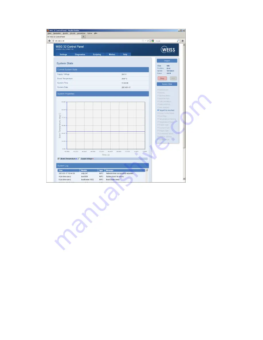
Via integrated help texts, the module’s web interface is intuitive to use. In the  upper area you will find a 

menu bar via which the individual pages can be called up. 

9.15


Access restrictions for the web user interface 

Depending on the network configuration, the module will be visible to everyone in the entire network and 

the configuration can thus be altered unchecked. 

To restrict access to the module's web interface, under "Settings” → “System Configuration" you can acti-

vate  access  restrictions  for  the  interface  and  create users  with  differing  access  rights.  If  this  is  activated, 

each user must be identified with a login name and personal password (Figure 28). Every user is assigned to 

one of the following user groups: 


User


Standard user. Cannot adjust settings, but can only access the pages under the menu options “Di-

agnostics“ and “Help“. 

Figure 27: Web interface for configuration and diagnosis 

Summary of Contents for WSG 32

Page 1: ...Mounting and Operating Manual Electrical Compact Gripper WSG 32 Firmware Version 4 0 0 Hardware Version 1 July 2015 ...

Page 2: ......

Page 3: ...ards 7 3 4 Personnel qualification 7 3 5 Safety Considerations 7 3 6 Notes on particular risks 7 4 Warranty 9 5 Scope of delivery 10 6 Accessories 11 7 Technical Data 12 7 1 Outer dimensions 12 7 2 Nominal mechanical data 13 7 2 1 Mechanical Finger Load 14 7 2 2 Gripping force 15 7 3 Nominal electrical data 17 7 3 1 Fuse 18 7 3 2 Power supply and CAN Bus optional 18 7 3 3 Ethernet 18 7 3 4 CAN Bus...

Page 4: ...ware limit switch 37 9 9 Fast Stops requiring acknowledgment 38 9 10 Log memory 39 9 11 Thermal monitor 39 9 12 Monitoring the drive current 40 9 13 Monitoring the supply voltage 40 9 14 Configuration and diagnosis via the web interface 41 9 15 Access restrictions for the web user interface 42 9 16 Command interface 43 9 17 Scripting 44 9 18 Resetting the configuration 44 9 19 Implementing the gri...

Page 5: ...le is done via a Web Interface supporting almost every common web browser Furthermore the WSG 32 comes standard with a sensor port in the base jaws Here gripper fingers can be connected with integrated sensors which are evaluated directly from the gripper control Weiss Robotics and authorized distributors provide standard ized finger as accessories which work directly with the gripper control For ...

Page 6: ...eldbus interface PROFINET Modbus TCP WSG Scripting Reference Manual Description of the optional script interpreter for the gripper control system Please find additional information about the warranty in our general terms and conditions available online at www weiss robotics com 2 2 Target audience Target audience for these instructions are plant manufacturers and operators who keep this and other ...

Page 7: ... 5 Reference to further information ...

Page 8: ...module and the top jaws are sufficiently dimensioned according to the use case It must be ensured that the environment is clean and the ambient temperature corresponds to the specifications catalogue Please observe the maintenance instructions see chapter 10 It must be ensured that the environment is free from splash and vapours as well as from abrasion or process dust Excepted are modules that ar...

Page 9: ...on by the operator to work on the module must have read and understood the complete assembly and operating manual especially the chapter 3 Basic safety notes This applies particularly to personnel only used occasionally such as maintenance personnel 3 5 Safety Considerations Avoid any operation that affects the function and reliability of the module Observe applicable on site safety and accident p...

Page 10: ... sure that no residual energy remains in the system Perform maintenance modifications and additions outside the danger zone For all work secure the unit against accidental operation Take a precautionary approach by maintenance and disassembly Only special trained staff should disassemble the module ...

Page 11: ...g conditions Intended use in 1 shift operation Observe the mandatory maintenance and lubrication intervals Observe the environmental and operating conditions Parts touching the work piece and wearing parts are not part of the warranty The module is considered defective if its basic function gripping is no longer given ...

Page 12: ... 10 5 Scope of delivery The scope of delivery includes WSG 32 068 servo electric 2 finger parallel gripper Operating manual CD with documentation and firmware ...

Page 13: ...ht angle Power supply cable length 5 m 6 pole M8 connector to free wire ends shielded Part No AL M8 6P 5M straight and AL M8 6PW 5M right angle Centering sleeves 06 0x5 35 outer diameter 6h6 item no ZH 6 0 5 35 PROFINET RT software license OPT WSG PN Universal Finger WSG F Force Measurement Finger WSG FMF Tactile Sensing Finger WSG DSA Please order accessories separately More accessories can be fo...

Page 14: ... 12 7 Technical Data 7 1 Outer dimensions Figure 2 Outer dimensions ...

Page 15: ...N 5 Gripping speed 5 mm s finger length 55 mm steel on steel Maximum gripping force N 50 Gripping speed 50 mm s finger length 55 mm steel on steel Weight kg 0 55 Workpiece weight kg 0 5 0 5 Finger length mm 120 at nominal force see Figure 3 Mass per finger kg 0 1 Tightness IP 40 DIN EN 60529 Ambient temperature C 0 50 Air humidity 0 90 Non condensing Repeatability mm 0 005 3σ deviation Gripping sp...

Page 16: ...ing table shows the maximum load of the finger The specified load may be applied simultane ously and in addition to the gripping force Mechanical Load Unit Min Typ Max Remark FZ N 50 MX Nm 1 6 MY Nm 1 6 MZ Nm 1 0 50 100 150 200 250 300 350 400 450 0 1 2 3 4 5 6 Gripping Speed mm s Finger position mm Acceleration 5000 mm s ...

Page 17: ...ng force is calibrated during the manufacturing process The actual gripping force de pends on gripping speed finger length and temperature Figure 6 shows the recommended gripping speed according to the desired gripping force The typical influence of the finger to the effective gripping force is shown in Figure 7 For a precise control of the gripping force use the Force Measurement Finger WSG FMF a...

Page 18: ...cation Figure 6 Recommended gripping speed steel on steel finger length 40 mm Figure 7 Gripping force over clamping height diagram 0 10 20 30 40 50 60 0 5 10 15 20 25 30 35 40 45 50 Gripping Speed mm s Gripping Force N 0 10 20 30 40 50 60 0 10 20 30 40 50 60 70 80 90 100 110 120 Gripping force N Clamping height mm F 25N F 50N ...

Page 19: ...dissipated via the screw contact surface Damage to the module is possible 7 3 Nominal electrical data Exceeding the specified nominal data can damage the module If in doubt please discuss your ap plication with our technical sales department Parameter Unit Min Typical Max Remark Clamping voltage V DC 22 24 28 Currend drawn when idle A 0 05 Current drawn when hold ing A 0 75 Gripping force 50N Posi...

Page 20: ...e module s GND pin as reference potential Figure 9 shows the pin assignments Requirement for the power supply Power supply 24 V DC 10 Ripple 150mVPP Available output current at least 3 A 7 3 3 Ethernet The Ethernet interface can be used both for commands as well as for configuration via the integrated web server It is presented via a 4 way M8 connector socket Figure 10 shows the pin assignments Wi...

Page 21: ...so lution of host names Interface specification Parameter Unit Min Typical Max Remark Transmission standard IEEE 802 3 Communication standard TCP IP IPv4 Transmission speed MBit s 10 100 Auto negotiated Transmission type Half duplex Auto MDIX yes 7 3 4 CAN Bus optional The module is available with an optional CAN Bus interface It is connected using the M8 connector of the power supply cf Figure 9 ...

Page 22: ... this memory integrated and are completely configured so that you just have to fit this finger to the module The fingers will then be auto matically detected the next time the system starts The sensor port supplies an operating voltage of 5 V 10 at max 200 mA The supply voltage is protected against short circuits and can be switched on and off from the gripper control system A short circuit in the...

Page 23: ...ibed as cen tering sleeve 06 0 x 5 35 outer diameter 6h6 Sensorport connector type Manufacturer ERNI type SMC B 12 terminal strip part number 154805 Counterpiece SMC Q 12 male low profile connector part number 154818 Sensor port connector pin assignments Pin number Name Direction Function 1 MOSI TXD OUT SPI UART Transmit data from the manual controller 2 nSSEL OUT Only SPI A low signal selects the...

Page 24: ...SO RXD IN SPI UART Received data 7 CFG SCL OUT Configuration bus clock line 8 NC not connected 9 5V OUT Operating voltage output 5V 200mA max 10 5V 11 GND OUT Mass 12 GND 7 4 Name plate The name plate is on the narrow side of the module above the connector Part Type WSG 32 Serial No XXXXX www weiss robotics com Figure 12 Name plate ...

Page 25: ...s When in holding mode the module constantly adjusts the gripping force to ensure a constant gripping force The surfaces which are screwed together must be capable of dissipating the resulting heat Risk of burns from hot surfaces Please ensure that the thermal coupling is good especially if the module is to apply high gripping forces over longer periods of time There is a risk of overheating Preve...

Page 26: ... would like to use an external relay to ensure that the gripping force is safely switched off cf safe torque off STO then the power and logic parts can be supplied separately The equivalent circuit for the power supply is shown in Figure 14 The power and logic supply are not electrically isolated so they must use the same power supply unit The common supply of load and logic is shown in Figure 15 ...

Page 27: ...circuit for the power supply Gripper Module 24V DRIVE 24V LOGIC GND Power Supply GND 24V 5A Figure 15 Connection type common supply to load and logic Gripper Module 24V DRIVE 24V LOGIC GND Power Supply GND 24V 5A Force off Figure 16 Connection type Supply to load separate from supply to logic ...

Page 28: ...ng the module please follow this sequence of steps 1 Using the Ethernet cable supplied connect the module to the existing Ethernet network or alterna tively to the network card in your PC or laptop The module s IP address is factory set to a static value of 192 168 1 20 Should you wish to operate several modules in the same network and or if this address is already in use then you will have to cha...

Page 29: ... after about 5 seconds it will start flashing quickly blue This signals that the module is booting After about 15 seconds the indicator will slowly flash white The module is ready for use 4 On your computer open its web browser and enter the address http 192 168 1 20 5 You will be presented with the module s configuration interface Figure 18 6 From the menu select the Motion Manual Control option ...

Page 30: ... the commissioning a Call up the Diagnostics System State page to check the module s supply voltage b On the Settings Command Interface page select the interface on which your module is to be operated c If necessary on the Settings Motion Configuration page enable automatic zeroing during startup Homing on Startup d On the Settings System page create a user with corresponding rights and activate t...

Page 31: ... you will have to restart the module To use addresses dynamically assigned via DHCP check the corresponding box In this case the module will automatically take its network configuration from a DHCP server Please note that if you use DHCP to dynamically allocate IP addresses there is no integrated way of finding out what IP address has been allocated This is why the DHCP server should be config ure...

Page 32: ...e module is already installed in the unit To guarantee proper operation the latest version of the firmware should always be installed in the module The latest firmware can be downloaded free of charge from www weiss robotics de The module has to be registered before download 9 2 Memory card The module s control unit is equipped with a tray for Micro SD memory cards Although all popular types SD an...

Page 33: ...he installed software are necessary to operate the module If you are con sidering to change the SD card please copy the contents of the original card to the new card with an appropriate card reader 9 3 Boot process The module has a boot loader which loads and runs the unit s software from the memory card when the unit is powered up The indicator for the operating state will light up blue during th...

Page 34: ...kly pulsating Executing a script A script is being executed by the control system Green quickly pulsating Warning One or more parameters have reached warning limits Please check the system s status via its web interface Yellow quickly pulsating Command received with no errors The module has received an error free command Green pulses once Error carrying out a command An error has occurred while re...

Page 35: ...module s current state can be called up at any time via the status word and the gripper state 9 5 1 Status word The current state of the gripper is summarized in the so called status word The status word can be read via the command interface command Get System State 40h via the web interface or by a script command Read System State Flags gripper state Figure 22 shows the display of the status word...

Page 36: ...g towards the part The detec tion of gripped items is active HOLDING A part is being held A part is being held with the configured force The monitor of the gripped part has been activated PART LOST A part has been lost The pre configured gripping force can no longer be applied presumably be cause the part to be gripped has been lost NO PART FOUND No part has been found When closing the gripper at ...

Page 37: ...te of the gripper is shown like the status word in the side bar of the web interface see Figure 22 The diagram in Figure 23 shows the possible transitions between the module s states IDLE PART LOST NO PART FOUND RELEASING POSITIONING ERROR Pre positioning command Grasp command Position reached Part detected and grasping force established No part detected at given width and within clamping range GR...

Page 38: ...9 7 Gripping part detection and grip monitoring The module is equipped with an integrated detector for parts to be gripped and a grip monitor which al lows reliable handling even for difficult parts without the use of external sensors To configure these func tions the following parameters are available on the web interface Settings Motion Configuration Parameter Description Part Width Tolerance Th...

Page 39: ...LE WORKPIECE Nominal Part Width Part Width Tolerance 2 0 Clamping Travel 2 Positive movement direction Figure 24 Parameters defining a grip 9 8 Software limit switch The module s travel can be limited via the software limit switch as shown in Figure 25 There is one limit switch for an inner range MINUS and one for an outer range PLUS If the software limit switches have been activated then position...

Page 40: ...ivated then only movements to leave this area will be possible You will find more information on this subject in the WSG Command Set Reference Manual and the WSG Scripting Reference Manual 9 9 Fast Stops requiring acknowledgment The module offers a so called Fast Stop to put itself into a defined state in case of an error or malfunction Fast Stops are displayed by setting the SF_FAST_STOP flag in ...

Page 41: ...d will be used and are displayed in chronological order If the memory is full the oldest events will be overwritten The log memory can be read out via the web interface Diagnostics System State It can also be copied to the SD card to be downloaded from the web interface via the integrated file manager 1 Open the web interface 2 In the menu go to Diagnostics System Information 3 Click the button Du...

Page 42: ... is a current error This error can only be acknowledged if there is no longer a current error For the documentation of the command to acknowledge the Fast Stop via the command inter face see the WSG Command Set Reference Manual 9 13 Monitoring the supply voltage To ensure the correct functioning of the module the supply voltage to its power section is continuously monitored If the measured voltage...

Page 43: ... no longer a high low voltage error For the documentation of the system status word and the command to acknowledge the Fast Stop via the command interface see the WSG Command Set Reference Manual 9 14 Configuration and diagnosis via the web interface The module has an integrated web server with a user interface for configuration and diagnosis To use this the module must be connected via Ethernet T...

Page 44: ...n thus be altered unchecked To restrict access to the module s web interface under Settings System Configuration you can acti vate access restrictions for the interface and create users with differing access rights If this is activated each user must be identified with a login name and personal password Figure 28 Every user is assigned to one of the following user groups User Standard user Cannot ...

Page 45: ...e can be used which is specified in the document GCL Reference Manual The CAN Bus interface supports a binary communications protocol which is described in detail in the document WSG Command Set Refer ence Manual This binary protocol can also be used over TCP IP and UDP For the control via the fieldbuses PROFINET and Modbus TCP a DPv0 compatible I O register space is sup plied with which the modul...

Page 46: ...le can also be reset using a button in the tray under the cover plate see Figure 20 To reset the module follow these steps 1 Remove the cover plate from the control tray 2 Press the configuration reset button The SD card s access LED will start to blink Keep the button pressed until the module restarts after about 5 seconds 3 The configuration has been reset to factory defaults 9 19 Implementing t...

Page 47: ...eed The gripper state changes to RELEASING Wait until the gripper state is IDLE Deal with errors on ERROR 6 Start again at 2 Dealing with errors What to do in case of an error actually depends a lot on the application but in general requires the user to do something The following section gives some hints 1 Does the returned status code differ from E_SUCCESS Evaluate the returned status code and ev...

Page 48: ... 46 ...

Page 49: ...ion The effect of foreign substances e g steam acids etc Clean the module at regular intervals with a dry cloth to remove all soiling and metal chips These typically collect in the depressions on the linear guides for the base jaws and on the edges of the housing Damage to the gripper is possible due to insufficient lubrication dry running if the gripper con stantly goes through short movements ev...

Page 50: ...equirements on the power supply Communication with the module is not possible Check the connections and communications cables Check the interface addressing e g IP address and Port settings Check the connection parameters Error message in the system the LEDs on the module illuminate yel low or red Check the module s operating state 11 2 Module stops abruptly Possible cause Remedy Power supply inte...

Page 51: ...Possible cause Remedy Power supply interrupted Check the power supply Communication with the module is not possible Check the connections and communications cable Check the network settings in the module Check the network settings in the computer ...

Page 52: ... machine is to be installed with the provisions of the Machinery Directive 2006 42 EC is confirmed Applied harmonized standards especially EN ISO 12100 1 Safety of machines Basic concepts general principles for design Part 1 Basic terminology methodology EN ISO 12100 2 Safety of machines Basic concepts general principles for design Part 2 Technical principles The manufacturer agrees to forward on ...

Page 53: ...ntioned in this document can be changed to improve our products without prior notice Used trademarks are the property of their respective trademark owners Our products are not intended for use in life sup port systems or systems whose failure can lead to personal injury ...

Reviews: