


43-
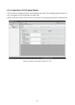
9.11.2
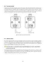
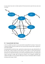
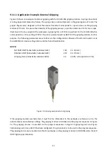
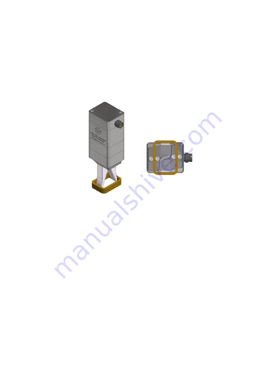
Application Example Internal Gripping
In an assembly process, a CLG 30-006 is to be used to pick up and insert a protective cover. Since the bushing
is to be inserted into a recess, it must be gripped on the inner surface. The gripping application is shown in
Figure 20. The illustration of the attachment to the movement axes and any compensating elements has
been omitted here. The cover with an inner dimension of 25 mm is gripped using the standard fingers (Figure
The gripper fingers are designed to hold the workpiece at a jaw position of 0.2 mm. To ensure the reliability
of the gripping process, a position tolerance of ±0.1 mm is specified. Gripping is to be performed with nominal
gripping force.
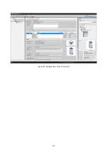
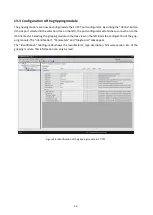
Since GRIP 0 is already occupied, the part is configured as GRIP 1 of the gripping module. For this purpose,
the following parameters are set either via the configuration software of the IO-Link master or via the
GRIPLINK-U1 device configurator available from Weiss Robotics:
GRIP 1:
NO PART LIMIT (Index 0x61, Subindex 0x01):
30
(= 0.3 mm)
RELEASE LIMIT (Index 0x61, Subindex 0x02):
0
(= 0 mm)
Gripping force (Index 0x61, Subindex 0x03):
100
(= 100%, corresponds to 30 N)
If the gripping module has been restarted, it must first be referenced. In this example, referencing to the
outside makes sense (= factory setting), since the fingers slightly overhang the inner edge of the base jaws.
This would result in referencing to the inside of the mounted gripper fingers, and the position value would
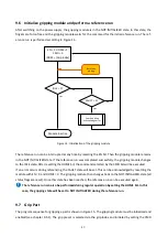
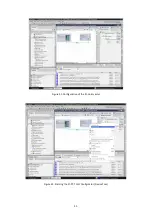
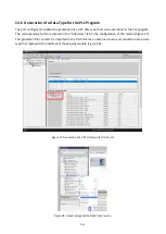
be subject to an offset. The initialization of the gripping module is carried out via the program sequence in
Figure 14. To grip the workpiece, the program sequence in Figure 15executed on the control side. With the
Figure 20: Application example internal gripping