Weishaupt WTC-GB 90-A Installation And Operating Instruction Download Page 63

9.1 Safety components

Vital safety components must be replaced as soon as they reach their predefined

lifetime.
The predefined lifetime is not the warranty time specified in the terms and conditions

of delivery and payment.

Safety 

component

Lifetime

according to construction

CEN-Standard

Printed circuit board (WCM-

CPU)

10 years or 250 000 operating cycles

EN 298-2003

Gas combi valve

10 years or 250 000 operating cycles

EN 126-1993

Gas pressure switch

10 years

EN 1854-1997

Air pressure switch

10 years

EN 1854-1997

Flue gas pressure switch

1 000 000 operating cycles

EN 1854-1997

Gasket

fan air outlet

10 years

EN 549 H3/B1

O ring 70 x 3

Gas valve/fan

10 years

EN 549 H3/B1

O ring 33 x 2

Gas valve/gas connection piece

10 years

EN 549 H3/B1

O ring 10.5 x 2.25

Pressure switch/gas connec-

tion piece

10 years

EN 549 H3/B1

Safety valve 3 bar

10 years

TRD 721-1997

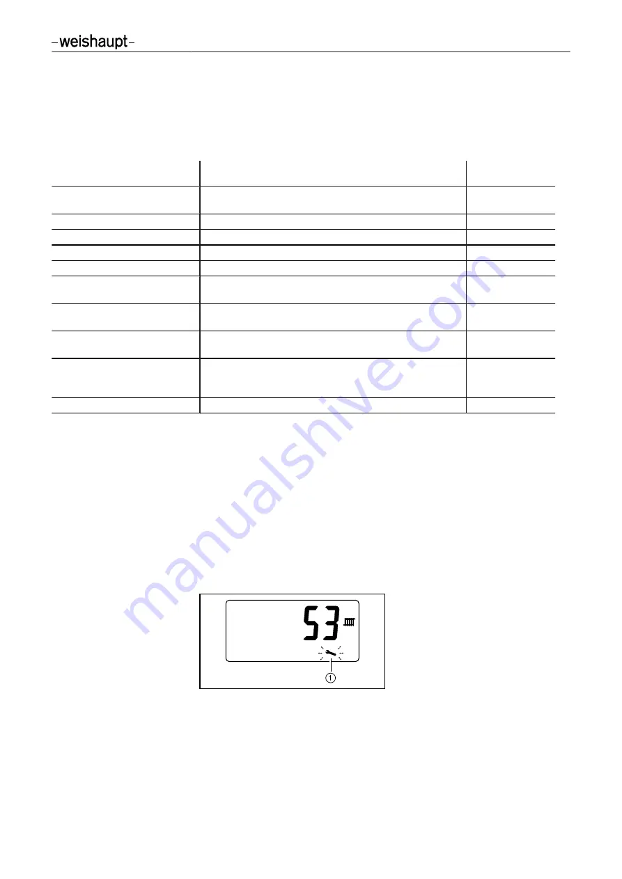
9.2 Servicing display

The time interval to the next service can be set. A flashing spanner will appear in the

display when the set interval has expired. 

Servicing

 is displayed, if a remote control

station is used.

Setting the service interval

Activate parameter level (see Ch. 6.3).

Set service interval via parameter 

70

.

Resetting the service display

The service display 

1

 must be reset after servicing.

Activate info level (see Ch. 6.3).

Select 

46

 in Info level i  (see Ch. 6.3.1).

Press enter button for 2 seconds.

Service display and timer will be reset.

Installation and operating instruction

Gas condensing boiler WTC-GB 90-A

9 Servicing

83266502 • 1/2010-08 • La

63-95

Summary of Contents for WTC-GB 90-A

Page 1: ...Installation and operating instruction Gas condensing boiler WTC GB 90 A 83266502 1 2010 08 ...

Page 2: ...e regulations of directives This product is labelled as follows Schwendi 14 07 2010 ppa ppa Dr Lück Denkinger Max Weishaupt GmbH Max Weishaupt Straße D 88475 Schwendi WTC GB 90 A WTC GB 120 A WTC GB 170 A WTC GB 210 A WTC GB 250 A WTC GB 300 A GAD 2009 142 EC LVD 2006 95 EC EMC 2004 108 EC BED 92 42 EEC CE 0085 Sprachschlüssel 02 ...

Page 3: ...Technical data 15 3 3 1 Approval data 15 3 3 2 Electrical data 15 3 3 3 Ambient conditions 15 3 3 4 Permissible fuels 15 3 3 5 Emissions 15 3 3 6 Rating 16 3 3 7 Heat exchanger 16 3 3 8 Flue gas system data 16 3 3 9 EnEV Product Characteristics 17 3 3 10 Dimensions 18 3 3 11 Weight 19 4 Installation 20 5 Installation 22 5 1 Requirements for the heating water 22 5 1 1 Permissible water hardness 22 ...

Page 4: ... 10 Inputs and outputs 48 6 11 Special system parameters 50 6 12 Chimney sweep function 51 7 Commissioning 52 7 1 Prerequisite 52 7 1 1 Check soundness of gas valve train 53 7 1 2 Check gas connection pressure 54 7 2 Adjusting the boiler 55 7 3 Change gas type 58 7 4 Calculating the burner rating 60 8 Shutdown 61 9 Servicing 62 9 1 Safety components 63 9 2 Servicing display 63 9 3 Check differenti...

Page 5: ... 12 1 Internal boiler wiring 90 12 2 Sensor variables 91 12 3 Pneumatic control lines 92 12 3 1 Air pressure switch connection diagram 92 12 3 2 Flue gas pressure switch connection diagram 92 12 4 Conversion table O2 CO2 93 13 Key word index 94 Installation and operating instruction Gas condensing boiler WTC GB 90 A 83266502 1 2010 08 La 5 95 ...

Page 6: ...TION Danger with low risk Non observance can cause damage to the equipment and injury to personnel Important information Requires direct action Result after an action Itemisation Range 1 1 2 Target group These installation and operating instructions are intended for the operator and quali fied personnel They should be observed by all personnel working on the unit Work on the unit must only be carr...

Page 7: ...ation commissioning operation and service of the unit alterations to the unit the installation of additional components which have not been tested with the unit the installation of combustion chamber inserts which impede full flame formation repairs which have been carried out incorrectly the use of non original Weishaupt parts unsuitable fuels defects in the inlet lines on non diffusion tight hea...

Page 8: ...ones Open doors and windows Close gas isolating valve Warn the inhabitants do not ring door bells Leave the building Inform the heating company or gas supplier from outside of the building 2 3 What to do if flue gas can be smelled Switch off the appliance and turn off the system Open doors and windows Inform heating company 2 4 Safety measures Rectify safety relevant defects immediately Replace sa...

Page 9: ...1 and Band 2 The gas supply pipe work should be suitable for the type and quality of gas and should be designed in such a way that it is not possible for liquids to form e g condensate Observe the vaporisation pressure and vaporisation tempera ture of liquid petroleum gas Use only tested and approved sealing materials whilst observing all process in formation Re commission the appliance when chang...

Page 10: ... 90 A WTC Weishaupt Thermo Condens G Fuel Gas B Type of construction floor standing 90 Ratings size 90 kW A Construction Installation and operating instruction Gas condensing boiler WTC GB 90 A 3 Product description 83266502 1 2010 08 La 10 95 ...

Page 11: ...ducting with sound attenuator 5 Connection expansion vessel Ø 22 mm 6 Siphon 7 Inlet and outlet tap 8 Condensate pan 9 Return collector with union nut 1 0 Heat exchanger section q Supply collector with union nut 1 Installation and operating instruction Gas condensing boiler WTC GB 90 A 3 Product description 83266502 1 2010 08 La 11 95 ...

Page 12: ... EAB 6 Boiler electronics WCM CPU 7 Gas pressure switch 8 Ionisation electrode 9 Ignition unit 0 Fan q Supply sensor w Flue gas sensor e Return sensor r Water level interlock t Air pressure switch z Flue gas pressure switch Installation and operating instruction Gas condensing boiler WTC GB 90 A 3 Product description 83266502 1 2010 08 La 12 95 ...

Page 13: ...d off W14 This function is only activated at a temperature of 45 C Flue gas sensor The fuel supply will be switched off if the flue gas temperature exceeds the value defined in parameter 33 factory setting 120 C The fan and pump run on is acti vated W16 Air pressure switch The air pressure switch monitors the fan pressure Before the pre purge phase is started the idle position of the switch contac...

Page 14: ...ed heating operation In the heating operation mode the delayed heating operation 9 is carried out first The heating capacity is restricted for the duration of the delayed time the delayed heating operation is omitted during DHW operation 6 Modulating operation The internal unit temperature regulator sets the speed setpoint for the fan 0 within the programmed load limits 7 Post purge Following ever...

Page 15: ...nsumption standby 7 W Internal unit fuse WCM CPU 6 3 AT External pre fuse 16 A Type of protection IP 20 Ignition electrode distance 4 0 mm 3 3 3 Ambient conditions Temperature in operation 3 30 C Temperature during transport storage 10 60 C relative humidity max 80 no dew point 3 3 4 Permissible fuels Natural Gas Liquid Petroleum Gas Propane 3 3 5 Emissions The condensing boiler complies with EN 2...

Page 16: ...sure loss Observe the pressure loss of the condensing boiler and the maximum throughput limit when determining the hydraulic sizing of the heating system Determine pressure loss using the diagram 0 350 400 300 250 200 150 100 50 0 1 3 5 7 9 2 4 6 8 1 Flow rate in m h 2 Pressure loss in mbar 3 3 8 Flue gas system data Residual supply pressure at flue gas outlet 7 157 Pa Flue gas mass flow rate 7 6 ...

Page 17: ... temperature 70 C 97 5 Hi 87 8 Hs Boiler efficiency factor at 30 rating and at return temperature 30 C 107 7 Hi 97 0 Hs Standby loss at 50 K above room temperature 0 33 271 W Installation and operating instruction Gas condensing boiler WTC GB 90 A 3 Product description 83266502 1 2010 08 La 17 95 ...

Page 18: ...m 1 Supply 1 union nut 2 Gas pipe Ø 22 mm 3 Condensate connection DN 25 4 Connection expansion vessel Ø 22 mm 5 Return 1 union nut 6 Safety valve connection G1 7 Air intake flue gas connection DN 160 110 Installation and operating instruction Gas condensing boiler WTC GB 90 A 3 Product description 83266502 1 2010 08 La 18 95 ...

Page 19: ...3 3 11 Weight Weight empty ca 117 kg Installation and operating instruction Gas condensing boiler WTC GB 90 A 3 Product description 83266502 1 2010 08 La 19 95 ...

Page 20: ...ideline Liquid Petroleum Gas Guideline Part 2 must be observed Remove front panel Open flap 1 on boiler control panel Undo screw 2 and remove front panel Transport For transportation pipes can be screwed in at 4 points Screw pipes to the transport points 1 Installation and operating instruction Gas condensing boiler WTC GB 90 A 4 Installation 83266502 1 2010 08 La 20 95 ...

Page 21: ... openings Minimum cross section for room air independent operation 230 cm2 Dimensions Observe the dimensions during the installation of the system see Ch 3 3 10 Minimum clearances Maintain a distance of minimum 50 cm to the walls on all sides of the boiler for in stallation and service work Adjust boiler position Level the boiler horizontally using the 4 screw feet 1 Installation and operating ins...

Page 22: ...f a separator 5 1 1 Permissible water hardness The permissible water hardness is determined in proportion to the fill and top up water quantity Determine from the diagram below whether water treatment measures are neces sary If the fill and top up water lies in the upper range of the limit curve treat the fill and top up water If the fill and top up water lies in the lower range of the limit curve...

Page 23: ...commissioning after 4 weeks of operation during the annual servicing If necessary adjust the pH value of the heating water by the addition of Trisodium Phosphate Softening cation exchanger CAUTION Damage to the unit due to raised pH value Corrosion could damage the unit Following the softening of the water by means of cation exchange the pH value must be stabilised due to the self alkalisation of ...

Page 24: ...expansion vessel Ø 22 mm 5 fill and return tap Filling the water CAUTION Damage to the condensing boiler due to unsuitable fill water Corrosion and scale could damage the system Adhere to the requirements for the heating water and the local directives see Ch 5 1 Open the shut off valves Gradually fill the heating system through the inlet tap system pressure minimum 1 3 bar Vent the system Check th...

Page 25: ... work sheet ATV DVWK A 251 and install a neutralisation system if required If the discharge point of the waste water system is located above the condensate drain Installing condensate lift pump Filling the siphon Run condensate hose on siphon to condensate outlet pipe Fill siphon with water via the flue gas outlet of the boiler until water flows from the condensate hose If an external siphon 1 is ...

Page 26: ...itted Installing the gas supply DANGER Risk of explosion due to leaking gas Gas leaks can lead to a build up of explosive gas air mixture With an ignition source present this can result in an explosion The gas supply should be installed with care and all safety instructions should be observed Close all shut off devices prior to commencing work and protect from accidental re opening Install gas sup...

Page 27: ...g regulations must be observed when designing the flue gas ducting Only approved flue gas systems may be used If the condensing boiler is connected to a chimney this must be damp proof Install the flue gas system at the flue gas connection 1 Measuring point in supply air annular gap 2 Flue gas test point The flue gas system must be sound Carry out a soundness test of the flue gas system Installati...

Page 28: ...tal braiding Separate ducts are provided for the separate installation of 230 V cables opposite to Bus and sensor cables SELV Feed the cables from the rear of the unit through the cable ducts to the connection box Assign the inputs and outputs according to application see Ch 6 10 Fit screen of Bus and external sensor cable to the designated screen connection terminals Connect the cables according ...

Page 29: ...Black Voltage supply 230 V AC 50 Hz H1 Turquoise Input 230 V AC 2 mA H2 Red Input 230 V AC 2 mA MFA 1 Purple Relay output 230 V AC max 3 A AC1 MFA 2 Purple Relay output 230 V AC max 3 A AC1 VA1 Brown Potential free relay output 230 V AC max 3 A AC1 eBUS Light blue WCM components FS EM KA COM B11 White De couple sensor NTC 5 kΩ 0 99 C B1 Green External sensor NTC 600 Ω 40 50 C B3 Yellow DHW sensor ...

Page 30: ...N MFA 1 L N MFA 2 VA1 eBUS 1 M B11 5 6 3 Connection additional safety valve LPG via output VA1 Observe the instructions for the electrical installation see Ch 5 6 Connect valve to connection diagram 230 V 50 Hz L N PE 16A 230V L H1 L E H2 L E 1 2 N L N MFA 1 L N MFA 2 VA1 eBUS 1 M B11 Installation and operating instruction Gas condensing boiler WTC GB 90 A 5 Installation 83266502 1 2010 08 La 30 9...

Page 31: ... Confirm selection confirm input 2 Dial knob Navigation through levels and parameters change values 3 Reset button Resetting fault conditions The system will be restarted if there is no fault 4 Switch S1 System ON OFF Installation and operating instruction Gas condensing boiler WTC GB 90 A 6 Operation 83266502 1 2010 08 La 31 95 ...

Page 32: ...s activated 3 DHW operation is activated 4 Fault 5 Service note 6 Flow temperature standard display parameters and values 7 Frost protection is activated 8 Standby 9 Summer setting or no heating operation 0 Heating at night setback value q Heating at setpoint value Display sensor interruption or short circuit Display burner rapid cycle interlock see Ch 6 7 Installation and operating instruction Ga...

Page 33: ...ergency operation are displayed 6 2 1 Display End User Level Various information can be called up in the end user level Turn the dial knob Tool bar appears Turn the dial knob Selection cursor alternates between the symbols 1 Flow temperature standby 2 Flow temperature standby 3 Type of operation S Summer setting W Winter setting 4 DHW temperature Installation and operating instruction Gas condensi...

Page 34: ...nge Factory setting 1 Normal supply temperature setpoint Setback flow temperature maximum flow tempera ture P 31 standby 60 C 2 Setback supply temperature setpoint Minimum supply temperature P 30 normal supply temperature 30 C 3 Type of operation S Summer W Winter W 4 DHW setpoint value 30 C 65 C DHW operation off 50 C 5 Manual start up chimney sweep function minimum load maximum load 6 Heating En...

Page 35: ...etting with the enter button Heating engineer level tool bar will appear 1 Info level 2 Parameter level 3 Fault history Turn the dial knob and set the selection cursor below the required level Press enter button Level will be activated Exit heating engineer level Turn the dial knob until ESC appears Press enter button Installation and operating instruction Gas condensing boiler WTC GB 90 A 6 Opera...

Page 36: ...boiler Flow setpoint value Cascade operation Ratings setpoint value Remote operation DDC temperature setpoint value Remote operation WCM FS WCM EM via N1 peak heat demand C C C i 15 Temperature setpoint value via N1 C 1 can be reset Info Actuators Unit i 20 Type of operation H Heating operation W DHW i 22 Pump rating i 23 Fan speed rpm x 10 Info Sensors Unit i 30 eSTL temperature C i 31 Flue gas t...

Page 37: ...operating hours h x 100 i 44 Software version WCM CPU i 45 Software version WCM CUI i 46 1 Time since last servicing h x 10 i ESC Exit menu 1 can be reset Reset system values Press enter button for 2 seconds Values will be reset Installation and operating instruction Gas condensing boiler WTC GB 90 A 6 Operation 83266502 1 2010 08 La 37 95 ...

Page 38: ...ard reporting of lockout 2 Pump heating and DHW operation 3 Heating circuit pump heating operation 4 DHW load pump DHW operation 6 DHW circulation pump via WCM FS 7 Heating circuit pump via WCM FS 1 1 2 8 Permanent voltage 9 Activation flue gas damper fixed when P 11 EA 2 P 14 Function variable output MFA 2 0 Forward reporting of operation safety valve LPG 1 Forward reporting of lockout 2 Pump hea...

Page 39: ...at exchanger Range of values Factory setting P 30 Minimum supply temper ature 8 C P 31 P 32 8 P 31 Maximum supply temper ature P 30 P 32 85 C P 32 79 P 32 Switching differential supply temperature 1 7 K 4 P 33 Switch off temperature flue gas duct 80 120 C 120 P 34 Burner rapid cycle inter lock 1 15 min deactivation 5 P 35 Ignition speed 50 70 60 P 36 Minimum load 24 P 37 24 P 37 Maximum load heati...

Page 40: ...y pump only 20 100 100 P 47 Optimisation de couple control Supply de couple tem perature only when P 43 2 1 7 K 2 P 48 Optimisation tempera ture differential control Supply return tempera ture only when P 43 2 10 22 K 20 P 49 Idleness temperature dif ferential control 1 62 s 4 Parame ters DHW Range of values Factory setting P 50 Temperature increase during DHW operation 10 30 K 10 P 51 Switching d...

Page 41: ...re parameter 31 Exit manual ratings setting Press enter button You will exit manual ratings setting The last rating set will remain activated for 2 minutes The time sequence of 2 minutes can be restarted by turning the dial knob in the heating engineer level within these 2 minutes This provides the possibility of calling up system values in the info level at the relevant rating Display system valu...

Page 42: ...meter level see Ch 6 3 Select parameter 10 Current configuration appears Press enter button Turn the dial knob until appears Press enter button New configuration is located and displayed Press enter button The configuration is stored Example External sensor has been removed Installation and operating instruction Gas condensing boiler WTC GB 90 A 6 Operation 83266502 1 2010 08 La 42 95 ...

Page 43: ...r to the north side or the north west side of the building half way up min 2 5 m Avoid direct solar radiation and heat up by external heat sources If necessary carry out a temperature adjustment of the external sensor via parameter 20 DHW operation DHW operation takes priority over the heating operation DHW preparation is carried out when the temperature in the water heater drops below the DHW set...

Page 44: ... If the contact is open the temperature is stipulated by the existing control variation When the heating operation with special level is activated Sn and the current flow temperature will be displayed Dynamic burner rapid cycle interlock The dynamic burner rapid cycle interlock prevents the burner from starting too often It functions depending on certain boiler temperatures and cannot be deactivat...

Page 45: ...ed at input N1 Temperature remote control 4 20 mA It is possible to use input N1 as current input 4 20 mA To do this a switchover must be made via a jumper on the circuit board DANGER Electric shock when working with voltage applied The consequence is serious injury or death Isolate unit from mains prior to carrying out work Switch off system Remove housing cover from connection box Change over re...

Page 46: ... out via a PWM control signal Without control signal the PWM pump control to 100 Connect control signal at plug see Ch 5 6 1 Standard control Here the pump rating is assigned to the required burner load The pump is operated at minimum load when the burner is switched off Set parameter 43 at 1 Set the modulation limits for the pump via parameter 44 and 45 Temperature differential control With this ...

Page 47: ... or feeder pump load pumps on eBus are active thermal protection via boiler frost protection External temperature system frost protection temperature parameter 23 Pump continuous run is deactivated DHW frost protection version W DHW temperature 8 C Burner is operated at minimum load Outputs MFA and VA are active if they are parametered as feeder pump DHW load pump or circulation pump DHW temperatu...

Page 48: ... immediately DHW loading is carried out DHW priority Cascade parameter 12 A E The output is activated by the cascade manager 8 Permanent voltage only parameters 13 14 The output is permanently active 9 Flue gas damper only parameter 13 The output is activated prior to burner start to open the flue gas damp er Input H1 Setting parameter 16 Description 0 Release of heat exchanger in heating op erati...

Page 49: ...he display shows W24 when the contact is closed For example this function can be used to connect a safety switch of a condensate lift pump 4 Return signal flue gas damper closed When the flue gas damper is closed a return signal is sent to H2 Installation and operating instruction Gas condensing boiler WTC GB 90 A 6 Operation 83266502 1 2010 08 La 49 95 ...

Page 50: ...controller start PWM 15 30 24 A10 Max fan speed boiler 6600 7200 rpm 6900 A11 Max speed change modulating up 60 360 rpm s 120 A12 Max speed change modulating down 60 360 rpm s 120 A13 Max speed change modulating down after burner start 30 360 rpm s 180 A14 Rating delayed heating operation 24 100 24 A15 Duration delayed heating operation 0 5 min 2 A21 1 Max temperature spread Flow B12 return B13 20...

Page 51: ...chimney sweep function remains active for 15 minutes 1 Supply temperature 2 Rating in Deactivate chimney sweep function Turn the dial knob ESC appears Press enter button Chimney sweep function is deactivated The standard display re appears after approx 90 seconds Installation and operating instruction Gas condensing boiler WTC GB 90 A 6 Operation 83266502 1 2010 08 La 51 95 ...

Page 52: ... of electrical components and of all wiring checked Boiler and heating system have been adequately filled with water and vented Siphon has been filled An adequate supply of fresh air is guaranteed The flue gas ducts and combustion air ducts are unimpeded All regulating control and safety devices are functioning and set correctly Heat demand is ensured Additional system related tests could be neces...

Page 53: ... pressure equalisation for 5 minutes Initiate a test period of 5 minutes Check pressure loss The gas section is sound if the pressure does not drop by more than 1 mbar DANGER Risk of explosion due to leaking gas Improper work can lead to escaping gas and explosions Tightly close screws after working on the test points of the gas combi valve Document result of the soundness test on the engineers re...

Page 54: ...lowly open isolating valve whilst checking the pressure increase Gas connection pressure exceeds 60 mbar pressure Immediately close isolating valve Do not start plant Inform system operator Gas connection pressure is insufficient Do not start plant Inform system operator DANGER Risk of explosion due to leaking gas Improper work can lead to escaping gas and explosions Tightly close screws after wor...

Page 55: ...nal sensor A external sensor no external sensor 1 If a de couple sensor has been fitted P3 will be displayed after approx 7 seconds Press enter button The configuration is stored The display shows W47 because the gas isolating valve is closed If the enter button is not activated within 30 seconds the configuration will be stored automatically after 24 hours The configuration can also be started ma...

Page 56: ...w 1 the O2 content only changes after approx 1 2 a rotation Set O2 content at the setting screw Inbus 2 5 1 to table Clockwise rotation O2 content increases Anticlockwise rotation O2 content decreases Set O2 content at minimum rating Manually drive rating to minimum see Ch 6 4 Check combustion and if necessary adjust Set O2 content at the setting screw Inbus 2 5 2 to table Anticlockwise rotation O...

Page 57: ...bustion values and settings in the commissioning record Inform the operator about the use of the equipment Hand the installation and operating manual to the operator and inform him that this must be kept on site The operator should be told that the installation must be serviced annually If the type of gas is different to the factory set type Apply the enclosed sticker for type of gas and gas press...

Page 58: ... setting screw Inbus 2 5 1 to table Clockwise rotation O2 content increases Anticlockwise rotation O2 content decreases Set O2 content at minimum rating Manually drive rating to minimum see Ch 6 4 Check and adjust combustion Set O2 content at the setting screw Inbus 2 5 2 to table Anticlockwise rotation O2 content increased Clockwise rotation O2 content reduces O2 minimum rating O2 maximum rating ...

Page 59: ...ustion values and settings in the commissioning record Inform the operator about the use of the equipment Hand the installation and operating manual to the operator and inform him that this must be kept on site The operator should be told that the installation must be serviced annually If the type of gas is different to the factory set type Apply the enclosed sticker for type of gas and gas pressu...

Page 60: ...uring time TM should be a minimum of 60 seconds Calculate operating volume VB using the following formula Calculate conversion factor Determine gas temperature tGas and gas pressure PGas at gas meter Determine air pressure PBaro from the following table Height above sea level m 0 100 200 300 400 500 600 700 800 900 1000 1100 1200 1300 PBaro in mbar 1013 1001 990 978 966 955 943 932 921 910 899 888...

Page 61: ... shut off devices during extended shut down periods The system must be drained if there is a risk of frost during extended shut down periods Installation and operating instruction Gas condensing boiler WTC GB 90 A 8 Shutdown 83266502 1 2010 08 La 61 95 ...

Page 62: ...t the combustion plant is serviced at least once a year Service work must only be carried out by qualified personnel with the relevant exper tise Depending on site conditions it may be necessary to inspect the installation more frequently During the service all system components with high wear and tear or with a specific life span should be replaced Weishaupt recommends a service contract is enter...

Page 63: ...years EN 549 H3 B1 O ring 33 x 2 Gas valve gas connection piece 10 years EN 549 H3 B1 O ring 10 5 x 2 25 Pressure switch gas connec tion piece 10 years EN 549 H3 B1 Safety valve 3 bar 10 years TRD 721 1997 9 2 Servicing display The time interval to the next service can be set A flashing spanner will appear in the display when the set interval has expired Servicing is displayed if a remote control ...

Page 64: ... parameter 37 if necessary set to 100 Manually drive to rating see Ch 6 4 Set rating to 70 Read differential pressure from measuring device If the pressure is above 1 2 mbar the test is ok If the pressure is lower Check the following components Hoses of the air pressure switch Burner tube for soiling Heat exchanger for soiling Air and flue gas ducting unimpeded If necessary reset parameter 37 afte...

Page 65: ...ace ignition electrode 2 and gasket 1 whilst observing the ignition electrode distance of 4 0 mm Ionisation electrode remove plug X14 4 and earth wire 5 from boiler electronics Remove bolts 2 Replace ionisation electrode 3 and gasket 1 Installation and operating instruction Gas condensing boiler WTC GB 90 A 9 Servicing 83266502 1 2010 08 La 65 95 ...

Page 66: ...clamp 6 on air intake pipe and push on to gas air interconnection Remove hoses on gas air interconnection Remove nuts 1 with spring washers on burner flange Remove burner flange with gas air interconnection 3 Remove gasket on burner flange 2 Remove burner tube 1 Remove deposits from combustion chamber Check burner tube for visible damage replace if necessary Installation and operating instruction ...

Page 67: ... the fibres of the burner fleece do not stick out too far in the area near the ionisation electrode danger of short circuit with ionisation electrode Refitting Refit burner tube in reverse order by fitting burner tube to locator pins in heat exchanger and ensuring correct align ment of groove pins replacing burner flange gasket and gas gasket and observing correct fitting of hoses see Ch 12 3 Inst...

Page 68: ...collector 4 Clean heat exchanger using the cleaning kit accessory Remove deposits from heat exchanger and condensate collector 2 Remove closing cap 3 and clean siphon Fill siphon with water Replace seals of service covers Close all covers Installation and operating instruction Gas condensing boiler WTC GB 90 A 9 Servicing 83266502 1 2010 08 La 68 95 ...

Page 69: ...ng hose from test point 1 on the condensate collector Check pressure measuring hose for damage Connect test equipment 2 Generate test pressure of 5 5 mbar The flue gas pressure switch functions correctly if the display shows F38 Reconnect pressure measuring hose Reset system using reset button Exit Standby mode Installation and operating instruction Gas condensing boiler WTC GB 90 A 9 Servicing 83...

Page 70: ...40 50 of the rating Slowly close gas isolating valve The gas pressure drops The flue gas pressure switch functions correctly if the burner switches off and the display shows W47 15 10 Installation and operating instruction Gas condensing boiler WTC GB 90 A 9 Servicing 83266502 1 2010 08 La 70 95 ...

Page 71: ...valve 4 and air intake collec tor 3 Undo and remove screws 1 and remove fan Refitting Refit fan in reverse order ensuring correct seating of O rings 2 and gasket 6 Tighten nuts 5 with a torque of 1 5 Nm The air intake collector 3 is glued together and must not be opened Installation and operating instruction Gas condensing boiler WTC GB 90 A 9 Servicing 83266502 1 2010 08 La 71 95 ...

Page 72: ...liminated The boiler does not lock out during a warning Read the warning code Rectify the cause of the warning with the aid of the table in chapter 10 3 1 If a warning appears more than once the system should be checked by qualified personnel Faults A fault is indicated with an F and a number in the display If a fault occurs the systems goes to lockout Read the fault code Rectify the cause of the ...

Page 73: ... is displayed Turn the dial knob to interrogate the system status Process value Unit 10 Operating phase 0 Burner off 1 Standby check fan 2 Prepurge speed achieved 3 Prepurge 4 Ignition speed achieved 5 Ignition 6 Burner in operation 7 Gas valve check 8 Post purge speed achieved and post purge 11 Rating 22 1 Setpoint speed pump 30 eSTL C 31 Flue gas temperature C 32 Ionisation signal µA 37 Return t...

Page 74: ...tting of gas combi valve Clean or replace burner tube see Ch 9 5 Check phase of voltage supply W22 Flame failure during operation the system goes to lockout with F21 after one failed restart Check the ionisation electrode and replace if necessary see Ch 9 4 Check O2 settings Clean or replace burner tube see Ch 9 5 W24 Input H2 is closed parameter 17 3 lockout function Check components connected to...

Page 75: ... module W86 Communication to EM 6 is faulty Check address Check the connection Replace the extension module W87 Communication to EM 7 is faulty Check address Check the connection Replace the extension module W88 Communication to EM 8 is faulty Check address Check the connection Replace the extension module W89 Remote control signal input N1 faulty Test the setpoint signal see Ch 6 7 Check the conn...

Page 76: ... contact of air pressure switch not in Standby Check air pressure switch and cable and re place if necessary Chimney draught too great F35 The supply sensor is defective Check the sensor and cable and replace if necessary F36 Water pressure insufficient Check system pressure and top up F37 return sensor defective Check the sensor and cable and replace if necessary F38 Flue gas pressure switch does...

Page 77: ...on WCM CPU and WCM CUI faulty Check the connection Rectify electromagnetic disturbance source 10 3 3 Operating problems Observation Cause Rectification Burner does not operate in spite of heat demand Burner rapid cycle interlock ac tivated eSTB supply sensor return sensor must lie within a temper ature range of 4 K Wait for the cooling down Check sensor and replace if necessary Whistling noises bu...

Page 78: ...16 1 05 1 02 1 11 1 08 1 17 1 17 1 03 1 08 1 24 1 03 1 15 1 14 1 15 1 14 1 01 1 04 1 12 1 06 1 16 1 13 1 22 1 19 1 21 1 18 1 20 1 02 1 02 1 05 1 23 1 09 1 10 1 10 1 09 Installation and operating instruction Gas condensing boiler WTC GB 90 A 11 Spares 83266502 1 2010 08 La 78 95 ...

Page 79: ...ate weishaupt 125 x 35 793 815 1 13 Flap operating panel 482 101 22 12 7 1 14 Attachment for soft closing hinge 482 101 22 11 7 1 15 Soft closing hinge 482 101 22 21 7 1 16 Locking washer Quicklock BQ3 431 803 1 17 Cable duct 45 x 30 x 510 482 001 22 20 7 1 18 Sticky tape 30 x 50 x 2 343 146 1 19 Cable tie with rivet 481 011 22 11 7 1 20 Cable holder WPC20 with anchor bolt 482 101 30 74 7 1 21 Spa...

Page 80: ...4 2 44 2 27 2 14 2 14 2 16 2 29 2 25 2 22 2 11 2 12 2 17 2 26 2 40 2 41 2 42 2 43 2 13 2 10 2 32 2 24 2 19 2 15 2 23 2 06 2 05 2 02 2 01 2 15 2 04 2 08 2 07 2 21 2 15 2 20 2 15 2 18 2 30 2 30 2 31 Installation and operating instruction Gas condensing boiler WTC GB 90 A 11 Spares 83266502 1 2010 08 La 80 95 ...

Page 81: ...0 220 2 22 Ring clamp for pressure switch 482 101 22 18 7 2 23 Edge trim plate 401 110 02 08 7 2 24 Traction relief clamp 790 528 2 25 Screen connection terminal SK8 735 569 2 26 Connection box W EAB with plug 482 001 22 02 2 2 27 Connection box housing top W EAB 482 001 22 03 2 2 28 Boiler electronics set WCM CPU WCM CUI 482 101 22 36 2 2 29 Coded plug BCC 482 001 22 11 2 2 30 Micro fuse 6 3 A IE...

Page 82: ... 3 47 3 32 3 34 3 33 3 38 3 22 3 19 3 16 3 17 3 23 3 21 3 20 3 46 3 40 3 42 3 01 3 03 3 04 3 06 3 05 3 10 3 11 3 40 3 41 3 40 3 39 3 24 3 02 3 08 3 12 3 13 3 26 3 25 3 27 3 28 3 29 3 37 3 30 3 31 3 24 Installation and operating instruction Gas condensing boiler WTC GB 90 A 11 Spares 83266502 1 2010 08 La 82 95 ...

Page 83: ...hanger 482 101 30 14 7 3 23 Seal service cover heat exchanger 482 101 30 15 7 3 24 Disk nut M6 A2G 412 508 3 25 Service cover condensate collector 481 401 30 02 7 3 26 Seal service cover condensate collector 481 401 30 05 7 3 27 Union nut G 1 1 4 siphon 481 011 40 19 7 3 28 Seal siphon union nut G 1 1 4 481 011 40 21 7 3 29 O ring for cap 482 101 30 59 7 3 30 Cap siphon 482 101 30 58 7 3 31 Closin...

Page 84: ...4 16 4 06 4 21 4 35 4 45 4 03 4 04 4 07 4 08 4 09 4 10 4 19 4 13 4 18 4 23 4 24 4 40 4 43 4 42 4 31 4 21 4 22 4 39 4 02 4 01 4 38 4 37 4 36 4 33 4 17 4 05 4 12 4 33 4 46 4 46 4 44 4 41 4 14 4 34 4 28 4 27 Installation and operating instruction Gas condensing boiler WTC GB 90 A 11 Spares 83266502 1 2010 08 La 84 95 ...

Page 85: ...2 001 30 52 7 4 22 O ring 70 x 3 NBR 70 482 001 30 37 2 4 23 Air intake collector 482 001 30 70 2 4 24 Compact gas combi valve 482 001 30 13 2 4 25 Hexagonal nut M4 DIN 985 5 411 104 4 26 Spring washer B 4 DIN 137 431 652 4 27 O ring 33 x 2 NBR 482 101 30 32 2 4 28 Gas connection piece G1 482 001 30 50 2 4 29 Screw M5 x 35 DIN 912 402 255 4 30 Screw M5 x 12 DIN 912 402 207 4 31 Pressure switch GW5...

Page 86: ...5 06 5 10 5 13 5 12 5 11 5 15 5 05 5 01 5 03 5 04 5 09 5 07 5 16 5 17 5 14 5 02 5 08 Installation and operating instruction Gas condensing boiler WTC GB 90 A 11 Spares 83266502 1 2010 08 La 86 95 ...

Page 87: ...82 001 22 23 2 5 09 Plug cable water level interlock 482 101 22 20 2 5 10 Plug cable B14 flue gas sensor 482 001 22 25 2 5 11 Plug cable SELV signals 482 001 22 21 2 5 12 Plug cable air pressure switch 482 101 22 24 2 5 13 Plug cable pressure switch flue gas 482 101 22 31 2 5 14 Plug cable eSTL B12 B13 482 001 22 22 2 5 15 Plug cable H1 H2 482 101 22 18 2 5 16 Plug cable mains 230V 482 101 22 19 2...

Page 88: ...6 01 Installation and operating instruction Gas condensing boiler WTC GB 90 A 11 Spares 83266502 1 2010 08 La 88 95 ...

Page 89: ...th cable Gasket ignition electrode Ionisation electrode Gasket ionisation electrode Gasket 20 x 29 x 2 1 Seals service cover heat exchanger Seal service cover condensate collector 482 001 00 16 2 Installation and operating instruction Gas condensing boiler WTC GB 90 A 11 Spares 83266502 1 2010 08 La 89 95 ...

Page 90: ...U WCM FS W EAB WCM CUI 6 3 AT 1 eSTB 2 Flow sensor 3 Return sensor 4 Flue gas sensor 5 Fan control 6 Gas pressure switch 7 Air pressure switch 8 Flue gas pressure switch 9 Water level interlock 0 Ionisation q Ignition unit w Fuel valves gas combi valve e Fan motor Installation and operating instruction Gas condensing boiler WTC GB 90 A 12 Technical documentation 83266502 1 2010 08 La 90 95 ...

Page 91: ... 7849 6 635 20 14800 20 6244 4 631 25 12000 25 5000 2 627 30 9800 30 4029 0 623 35 8300 35 3267 2 618 40 6600 40 2665 4 614 45 5400 45 2185 6 609 50 4500 50 1802 8 605 55 3800 55 1494 10 600 60 3200 60 1245 12 595 65 2700 65 1042 14 590 70 2300 70 876 16 585 75 2000 75 740 18 580 80 1700 80 628 20 575 85 1500 85 535 22 570 90 1300 90 457 24 565 95 393 26 561 100 338 28 556 105 292 30 551 110 254 3...

Page 92: ...off pressure 1 0 0 7 mbar 3 Air intake collector 4 Gas combi valve 12 3 2 Flue gas pressure switch connection diagram P1 1 Flue gas pressure switch release pressure 5 5 mbar 2 Condensate collector Installation and operating instruction Gas condensing boiler WTC GB 90 A 12 Technical documentation 83266502 1 2010 08 La 92 95 ...

Page 93: ...10 1 12 0 3 0 10 0 9 9 11 7 3 4 9 8 9 6 11 5 3 8 9 6 9 4 11 2 4 2 9 4 9 2 11 0 4 6 9 1 9 0 10 7 5 0 8 9 8 8 10 4 5 4 8 7 8 5 10 2 5 8 8 5 8 3 9 9 6 2 8 2 8 1 9 7 6 6 8 0 7 9 9 4 7 0 7 8 7 7 9 1 7 4 7 6 7 4 8 9 7 8 7 4 7 2 8 6 8 2 7 1 7 0 8 4 Installation and operating instruction Gas condensing boiler WTC GB 90 A 12 Technical documentation 83266502 1 2010 08 La 93 95 ...

Page 94: ...6 External sensor 43 F Fan 12 71 Fan speed 16 Fault conditions 72 Fault history 73 Faults 72 Filling the water 24 Flow limit 8 Flow rate 8 Flue gas connection 11 18 Flue gas mass flow rate 16 Flue gas pressure switch 12 13 Flue gas sensor 12 13 Flue gas system 16 27 Flue gas temperature 16 Flue gas test point 27 Flue gas testing 56 58 Frost protection 47 Fuel 15 Function 14 Fusing 15 G Gas charact...

Page 95: ...ice set 89 Servicing 62 Servicing interval 62 Shut down 61 Shutdown time 61 Siphon 11 25 Smell of flue gas 8 77 Smell of gas 8 Sound attenuator 11 Soundness test 53 Spanner 63 Spare part 79 Special level 44 Standard efficiency 16 Standards 15 Standby loss 17 Storage 15 Supply collector 11 Supply sensor 12 Supply voltage 15 System frost protection 47 T Tap 47 Temperature 15 Temperature differential...

Page 96: ...ntally friendly heating Fuel Gas or oil as desired Thermo Condens The innovative condensing boilers with the SCOT system Efficient low in emissions versatile Ideal for domestic heating Floor standing gas condensing boiler with ratings of up to 1200 kW cascade for higher heat demands Heat pumps The heat pump programme offers solutions for utilisation of heat from air soil and ground water The syste...

Reviews: