WI-GTWY-9-xxx Wireless Gateway V1.18
135
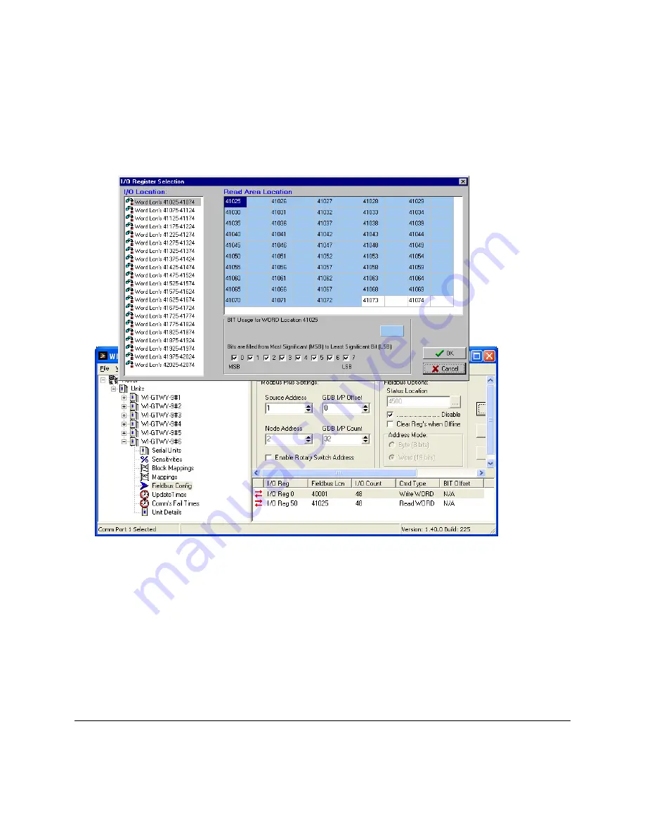
Count” parameters. In the above example, the values of the Offset = 0 and Count = 32,
indicating that the entire 32 word Global Data broadcast from the Source Unit will be read into
fieldbus interface registers 41025 – 41056. Other nodes on the network can write to the
remaining registers (41057 – 41072) only by using the Modbus point-to-point Write Register
commands described in section 4.14.3. NOTE – the point-to-point Write Register commands can
not
be used to write to the Global Data Input registers 41025 – 41056.
Finally, it must be taken into consideration that the WI-GTWY-9-xxx Modbus Plus module
dynamically adjusts the 4X register range available to the network depending on the fieldbus
mappings configured. The WI-GTWY-9-xxx will terminate the available 4X register range at the
last mapped 4X register for both the read and write area. In the example above this means that
the only 4X registers that are available to the Modbus Plus network are 40001 – 40048 and
41025 – 41072.
NOTE – considering this constraint, it is still strongly advised to use fieldbus interface registers
always starting at the lowest addressed locations, thus limiting unnecessary processing overhead
on the WI-GTWY-9-xxx.
4.15
Connecting WI-I/O-EX-1-S-1x Serial I/O
NOTE – Serial I/O Expansion is only possible for WI-GTWY-9-xxx Firmware versions 1.50
onwards.


