background image

15

NORTH AMERICA

SECTION 5: ELECTRICAL INSTALLATION

Fig 5.0.3 Solenoid Loom 

Fig 5.0.1 Dual Switch Assembly

Fig 5.0.2 I-Lock Controller 

The I-Lock Controller, Dual Switch Assembly and Solenoid Loom are designed to enable a “plug & 

play” electrical installation process.

• 

Determine a suitable position for the I-Lock Controller. Ensure the position is a dry location and 

easily accessible. Mount into position. (Caution - Do not over tighten fixing screws)

• 

Find two spare locations in the machine console, preferably side by side, to insert the dual 

rocker switches. 

•  Route the switch wires to the I-Lock Controller. Connect the corresponding male spade fitting to 

the female connector on each of the assemblies.

• 

Locate a switched (fused) power source from within the console of the carrier machine. Connect 

the RED power lead on the Dual Switch Assembly to the power source.

• 

Find a suitable earth location (negative) and connect the BLACK wire from the I-Lock Controller.

• 

Plug the Solenoid Loom into the I-Lock Controller.

• 

Route the Solenoid Loom from the I-Lock Controller position through to the engine compartment 

where the I-Lock Solenoid Valve is located.

• 

Connect the RED labeled DIN Plug to the “WEDGE” solenoid. 

• 

Connect the BLACK labeled DIN Plug to the “SAFETY” solenoid.

•  Ensure that all electrical looms are routed and fixed securely using cable ties where required.
• 

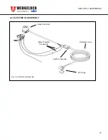
NOTE: See Electrical Assembly (Fig 6.2.2)

5.0 ELECTRICAL INSTALLATION

The I-Lock Coupler must be operated utilizing the I-LOCK CONTROLLER, DUAL SWITCH 

ASSEMBLY and SOLENOID LOOM. The proprietary electrical components have been 

designed in conjunction with the functionality and operation of the coupler safety features. 

The built in “Timer” and “Operational Sequences” controlling the solenoid valves are 

features which provide the operator and fellow co-workers a safe work environment during 

attachment change over.

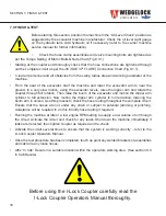
Failure to utilize the proprietary electrical components with the I-Lock Coupler could result in coupler 

malfunction, causing serious harm or even death.  (Fig 5.0.1 & 5.0.2 & 5.0.3)

Summary of Contents for I-LOCK MINI COUPLER

Page 1: ... new Wedgelock Coupler fitted with the I LOCKTM Safety Device requires the installation of a third hydraulic line please follow the instructions carefully S P E C I A L N O T E Dipper Arm Hoses Components Boom Arm Hoses Components Boom Base To Valve Hoses Components Pump Tank Hoses Components Cabin Mounted Components NORTH AMERICA ...

Page 2: ......

Page 3: ... sleeve 13 7 After hose routing is completed it will be easy to determine the best final mounting location for the coupler control valve 11 14 8 Route hoses from valve ports to hoses on boom and join with unions 14 9 Locate and connect pressure line from test port on pump to P port on valve 14 10 Locate and connect hose from hydraulic tank return line to T port on valve 14 11 Locate mounting posit...

Page 4: ...ON 10 4 1 FITTING THE HOSE CLAMP BRACKET 10 4 2 THE I LOCK CONTROL VALVE 11 4 3 INSTALLING THE CONTROL VALVE 11 4 4 HOSE ROUTING 12 4 5 HOSE ROUTING DIPPER ARM 12 4 6 HOSE ROUTING BOOM 13 4 7 HOSE ROUTING BOOM TO VALVE 14 4 8 HOSE ROUTING VALVE TO PUMP TANK 14 SECTION 5 ELECTRICAL INSTALLATION 5 0 ELECTRICAL INSTALLATION 15 SECTION 6 ASSEMBLIES 6 0 LOOSE HOSE KIT ASSEMBLY 16 6 1 PRE CRIMPED HOSE K...

Page 5: ... be installed Check that the carrier machine is positioned on level ground Check that you have absorbent materials available to soak up any fluid spills Dispose of any used materials in a safe and environment friendly manner Power off the carrier machine If the machine has been working ensure that it has cooled down adequately prior to commencing any part of the installation procedure Before carry...

Page 6: ...aks tighten and adjust accordingly Avoid contact with hydraulic fluids and high pressure oils use cardboard or similar as a backing when checking for leaks Oil spills are sometimes unavoidable Contain all fluid spills with appropriate absorbent materials and dispose accordingly Immediately clean affected areas to minimize safety risks When operating plant and machinery keep people and property wel...

Page 7: ...ments pinned to the carrier machine Dipper Arm Operator View Coupler C Section Coupler C Section FIG 3 1 1 Coupler Orientation Fig 3 1 1 Coupler Orientation NORTH AMERICA SECTION 1 SAFETY 3 0 SAFETY DURING COUPLER INSTALLATION Always use the correct PPE when removing attachments from carrier machines Stand well clear of machinery that is in motion at all times NEVER place hands or fingers near pin...

Page 8: ...the correct position if fitted NOTE ORIGINAL OEM LINKAGE PIN MUST BE USED Page 7 SECTION 3 COUPLER INSTALLATION 3 2 REMOVE THE EXISTING BUCKET Before you fit the coupler to the carrier machine you have to firstly remove any existing attachment from the dipper arm Fig 3 2 1 Place the bucket or attachment in a safe position on the ground Undo the pin retention systems holding the dipper pin and link...

Page 9: ...HECK CLEARANCES IF THERE ARE ANY SIGNS OF INTERFERENCE STOP IMMEDIATELY AND CONTACT YOUR WEDGELOCK DEALER Page 8 SECTION 3 COUPLER INSTALLATION 3 4 FITTING THE COUPLER Dipper Pin Place o rings over ear plates of coupler to hold in position until ready for final placement Carefully raise the dipper arm of the carrier machine so that the weight of the coupler is off the ground Ensure that the dipper...

Page 10: ... to the main dipper pin to minimize hose length 4 1 FITTING THE HOSE CLAMP BRACKET Once the optimum position has been determined clean and prepare the surface of the dipper arm to be welded Lightly tack the hose clamp bracket into position carefully tacking only the ends of the bracket Refer to welding precautions and carrier machine service manual for welding instructions Fit all 3 Blue hoses to ...

Page 11: ...e retract EXT primary wedge extend SAFETY safety knuckle release For pressure settings refer to the pressure settings chart on page 20 For service details regarding the control valve refer to the service section in the Operators Manual 4 3 INSTALLING THE CONTROL VALVE Identify the pump that delivers flow to the BUCKET CURL CYLINDER of the carrier machine This is the most common pump used for hydra...

Page 12: ...in routing the hoses from the coupler end of the machine to the engine compartment end If using a Pre Crimped Hose Kit follow the instructions ensuring that each color coded hose is positioned as required If using a Lose Fitting Kit you can use the color coded instructions as a guide to achieve the same results 4 5 HOSE ROUTING DIPPER ARM Connect the Dipper Arm hoses to the coupler cylinder and th...

Page 13: ...ided for the Dipper Use the Zip Ties provided for securing the coupler hoses to the boom Prepare the surface of the boom for welding in these locations Weld clamp assemblies ensuring that only the vertical ends of the clamp brackets are welded Touch up paint the boom and clamp to match the carrier machine color Tighten all hose joints between the coupler cylinder and the dipper arm to boom connect...

Page 14: ... kit See Control Valve Assy Fig 4 2 1 Utilizing a TEST PORT on the pump that delivers hydraulic pressure to the bucket curl cylinder circuit see section 4 3 connect the hose from the check valve on the P port to the test port Locate an existing tank line hose on the main return manifold or hydraulic tank Disconnect the existing hose and install a tee fitting Reinstall the existing hose onto one en...

Page 15: ...CK wire from the I Lock Controller Plug the Solenoid Loom into the I Lock Controller Route the Solenoid Loom from the I Lock Controller position through to the engine compartment where the I Lock Solenoid Valve is located Connect the RED labeled DIN Plug to the WEDGE solenoid Connect the BLACK labeled DIN Plug to the SAFETY solenoid Ensure that all electrical looms are routed and fixed securely us...

Page 16: ...it Assembly HYDRAULIC COUPLER I LOCK SAFETY SYSTEM Pump Tank Hoses Dipper Arm Hoses Boom Hoses Coupler Hoses MACHINE SPECIFIC SETTINGS CHECK VALVE I LOCK SAFETY SYSTEM COUPLER CONTROL VALVE 12V OR 24V HYDRAULIC COUPLER I LOCK SAFETY SYSTEM MACHINE SPECIFIC SETTINGS CHECK VALVE I LOCK COUPLER CONTROL VALVE Pump Tank Hoses Dipper Arm Hoses Boom Hoses Coupler Hoses ...

Page 17: ...17 NORTH AMERICA Fig 6 2 2 Electrical Assembly 6 2 ELECTRICAL ASSEMBLY SECTION 6 ASSEMBLIES I Lock Controller Male Female Connectors Solenoid Loom Earth Connection Din Plugs ...

Page 18: ...r through full rotation Then raise the boom of the excavator and motion the dipper arm cylinder to full extension Now motion the dipper arm cylinder to full retraction lowering the boom arm in unison Use this process to check the hose routing throughout the complete circuit Ensure that the hoses are not under any strain or subject to potential jamming or pinching Assistance will be required to do ...

Page 19: ...ffixed in a suitable location within the operators working area For replacement decals please call your nearest Wedgelock dealer Fig 8 0 1 Warning Decal 8 0 2 I Lock Coupler Oerating Decal Fig 8 0 1 Warning Decal Fig 8 0 2 I Lock Coupler Operation Decal SECTION 8 IN CAB DECALS ...

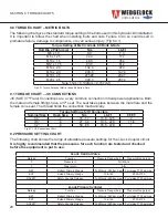
Page 20: ... 132 0 97 3 M16 x 2 0 200 0 147 4 M18 x 2 5 275 00 202 7 M20 x 2 5 390 0 287 4 Note 1Nm 0 102kgm 0 737 lb ft Torque Setting of JIC Connectors Nominal Size Dash Size Nm Lb Ft F F F T 1 4 4 15 17 10 8 12 5 2 3 8 6 27 30 19 6 22 0 1 1 4 1 2 8 59 65 45 5 47 8 1 9 2 PRESSURE SETTING CHART The following chart shows the range of allowable pressure settings for the I Lock Coupler circuit It is highly reco...

Page 21: ......

Page 22: ...7294 0187 USA 800 CASCADE 227 2233 Tel 503 669 6257 www wedgelockusa com Cascade and Wedgelock are registered trademarks of Cascade Corporation Cascade Corporation 2013 All rights reserved Form 6843145 150 GE 07 13 NORTH AMERICA ...

Reviews: