14
NORTH AMERICA
SECTION 4: HYDRAULIC KIT INSTALLATION
4.7 HOSE ROUTING – BOOM TO VALVE
•
Connect the RED color coded hoses for the Boom to Valve to the boom hoses at the base end
of the boom.
•
Route the hoses through to the pump compartment towards the control valve following the
existing hose routing from the boom end.
•
Trace the hoses from the quick coupler cylinder right through to the end where they connect to
the valve to determine the correct hose for each port position on the valve.
•
Connect the hose ends to the control valve ensuring that they are connected to their respective
port positions relative to the cylinder.
• Cable tie Boom to Valve hoses to existing hoses where appropriate and coil any excess hose in
the pump compartment. Ensure that the hoses are not bound up or under any strain.
• Tighten all hose joints and fittings between the lower boom end and the control valve.
4.8 HOSE ROUTING – VALVE TO PUMP / TANK
•
Using the BLACK color coded hoses from the install kit connect the hose ends to the valve
marked P (Pump) and T (Tank).
•
The supplied Check Valve should be connected directly to the “P” (Pressure) port on the I-Lock
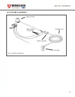
Control Valve with the fittings provided in the kit. (See Control Valve Assy Fig 4.2.1)
•
Utilizing a “TEST PORT” on the pump that delivers hydraulic pressure to the bucket curl cylinder
circuit (see section 4.3) connect the hose from the check valve on the “P” port to the test port.
• Locate an existing tank line hose on the main return manifold or hydraulic tank. Disconnect the
existing hose and install a tee fitting.
• Reinstall the existing hose onto one end of the tee and then connect the new tank line hose from
the control valve “T” port to the other end of the tee.
• Cable tie hoses to existing hoses where appropriate and coil any excess hose if required. Ensure
that the hoses are not bound up or under any strain.
• Tighten all hose joints and fittings between the control valve and the pump and tank.
NOTE 1: When utilizing a “Pre-Crimped” or “Loose” hose kit supplied by Wedgelock we have
endeavored to supply the majority of the fittings required to carry out a complete install of an I-Lock
Coupler, however due to the vast array of different carrier machines, fitting types and port sizes, not
all circumstances may be accounted for. In instances where the fittings supplied do not match the
port size or the type of carrier machine that this install is being carried out on please contact your
nearest machinery dealer or hydraulic fittings provider for the additional appropriate component(s).
NOTE 2: See Hydraulic Schematic (Fig 6.0.1)


