


20
NORTH AMERICA
SECTION 9: TORQUE CHARTS
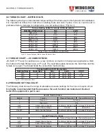
9.0 TORQUE CHART – METRIC BOLTS
The following chart gives the standard torque setting of the bolts used in this hydraulic kit installation.
It is important to follow the chart when installing bolts and nuts. Failure to do so could result in
premature failure, damage to components, or even serious injury. (Fig 8.0.1)
Fig 9.0.1 Torque Setting of Metric Grade 8.8 Bolts & Nuts
9.1 TORQUE CHART – JIC CONNECTIONS
JIC (SAE 37º Flare) Connections are a very common connection in fluid power applications. Both
the male and female fittings have a 37º seat. The seal takes place between the male flare and the
female cone seat. The thread holds the connection mechanically.
Fig 9.1.1 JIC Connections Chart
Torque Setting of Metric Grade 8.8 Bolts & Nuts
Bolt Dia x Pitch (mm)
Nm
Lb.Ft
M6 x 1.0
9.9
7.3
M8 x 1.25
24.0
17.7
M10 x 1.5
48.0
35.4
M12 x 1.75
83.0
61.2
M14 x 2.0
132.0
97.3
M16 x 2.0
200.0
147.4
M18 x 2.5
275.00
202.7
M20 x 2.5
390.0
287.4
Note: 1Nm = 0.102kgm = 0.737 lb.ft
Torque Setting of JIC Connectors
Nominal Size
Dash Size
Nm
Lb.Ft
F.F.F.T.
1/4”
-4
15 - 17
10.8 - 12.5
2
3/8”
-6
27 - 30
19.6 - 22.0
1 1/4
1/2”
-8
59 - 65
45.5 - 47.8
1
9.2 PRESSURE SETTING CHART
The following chart shows the range of allowable pressure settings for the I-Lock Coupler circuit.
It is highly recommended that the pressures for each function are tested and checked
before the equipment is put to use.
I-Lock Control Valve
Marking
Function
Pressure Range (bar)
Pressure Range (psi)
P
Pressure In
Full Mains
T
Tank return
N/A
RET
Retract Primary Wedge
Full Mains (260 bar max) Full mains 3750 psi max
EXT
Extend Primary Wedge
138-145
2000-2100
SAFETY
Safety Knuckle Release
Full Mains (260 bar max) Full mains 3750 psi max
I-Lock Primary Cylinder
Marking
Function
Pressure Range (bar)
Pressure Range (psi)
RET
Retract Primary Wedge
Full Mains (260 bar max) Full mains 3750 psi max
EXT
Extend Primary Wedge
138-145
2000-2100
SAFETY
Safety Knuckle Release
Full Mains (260 bar max) Full mains 3750 psi max